Introduction
In the high-stakes world of RF (Radio Frequency), microwave, and high-speed digital design, the substrate is more than just a carrier; it is a critical component of the circuit's electrical performance. Rogers PCB manufacturing has emerged as the industry gold standard for applications where traditional FR-4 materials fail to meet signal integrity and thermal stability requirements.
This comprehensive guide explores the complexities of Rogers PCB fabrication, material selection, and the advanced technical strategies required to produce high-reliability boards for 5G, aerospace, and automotive radar systems.
The Foundation of High-Frequency Success
Selecting a substrate is no longer just about mechanical support; it is about signal integrity. Rogers materials, such as the RO4000 and RO3000 series, offer a controlled dielectric constant (Dk) and an ultra-low dissipation factor (Df) that are essential for minimizing energy loss in RF circuits.
However, understanding the raw material is only the starting point. To truly leverage these high-end laminates, one must understand the intersection of material science and fabrication. For a deeper look into the standards and material properties that define this field, our definitive guide to high-frequency excellence in Rogers PCB manufacturing provides an essential roadmap for selecting the right substrates for 5G, radar, and satellite systems.
Why Rogers PCB Manufacturing is Different from FR-4
Standard FR-4 is composed of epoxy resin and woven glass. While cost-effective, its high dissipation factor (Df) and inconsistent dielectric constant (Dk) lead to significant signal loss at frequencies above 3GHz.
Rogers PCB manufacturing utilizes specialized ceramic-filled, hydrocarbon, or PTFE (polytetrafluoroethylene) laminates. These materials offer:
-
Low Signal Loss: Minimal Df ensures high-frequency signal clarity.
-
Dk Stability: Consistent dielectric constant across temperature and frequency ranges.
-
Lower Moisture Absorption: Ideal for aerospace and harsh environment applications.
-
Superior Thermal Management: Higher thermal conductivity compared to standard substrates.
Key Rogers Material Families and Their Applications
Choosing the right laminate is the first step in successful Rogers PCB manufacturing. The most common series include:
| Material Series | Core Composition | Key Benefit | Typical Application |
| Rogers 4000 Series | Ceramic-filled Hydrocarbon | FR-4 process compatible, low loss | 5G Base stations, LNBs |
| Rogers 3000 Series | PTFE-based (Teflon) | Exceptional electrical stability | Automotive Radar (77GHz), Satellites |
| Rogers 5000/6000 Series | Glass-reinforced PTFE | Highest reliability, aerospace grade | Military Guidance Systems, UAVs |
| Rogers 2000 Series | PTFE with Ceramic Filler | Ultra-low Dk, lowest loss | Specialized Microwave components |
While the table above highlights common uses, identifying the perfect laminate for high-speed or thermal-heavy designs requires a deeper dive into technical specifications. Our comprehensive Rogers PCB guide provides the detailed analysis needed to make an informed choice.
Navigating the Complexities of Rogers Fabrication
Manufacturing with Rogers laminates involves significantly different mechanical and chemical processes compared to standard epoxy-glass boards.
Drilling and Mechanical Processing
PTFE-based materials are notoriously "soft." If standard drilling parameters are used, the friction heat can cause resin smear, which ruins the electrical connection of the plated through-holes (PTH). Specialized drill bit geometries and cooling cycles are mandatory in Rogers PCB manufacturing to ensure clean, burr-free holes.
Surface Activation and Plasma Etching
Because Rogers substrates are designed to be chemically inert and moisture-resistant, they do not bond easily with copper plating. Manufacturers must use plasma etching or sodium-naphthalenate treatments to "activate" the surface. Without this, the copper layers risk delamination during thermal cycling.
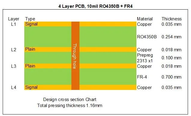
The Challenge of Hybrid Stack-ups
Many modern designs use "Hybrid PCBs"—stacking Rogers layers for high-speed signals and FR-4 layers for power and ground. This requires a master-level understanding of the Coefficient of Thermal Expansion (CTE). Because these materials expand at different rates, the lamination press cycle must be meticulously tuned to prevent board warping.
When these technical variables collide, production can often stall. For engineers facing specific fabrication bottlenecks, we have compiled a tactical manual for troubleshooting common manufacturing challenges with Rogers PCBs, focusing on registration accuracy and thermal expansion management during complex multilayer lamination.
Quality Assurance: Eliminating Defects Before They Occur
In Rogers PCB manufacturing, the cost of raw materials is significantly higher than in standard production. Consequently, a high scrap rate can be financially devastating. Maintaining a high-yield environment requires a shift from "inspection" to "prevention."
Common defects like blistering, inner-layer separation, or oxidation are often symptoms of microscopic process deviations. To ensure long-term reliability in mission-critical applications, it is vital to implement a rigorous protocol for identifying and preventing Rogers PCB manufacturing defects. By mastering the nuances of copper bonding and moisture control, fabricators can eliminate the most frequent causes of high-frequency circuit failure.
Critical Technical Challenges in High-Frequency Fabrication
Signal Integrity and Impedance Control
In Rogers PCB manufacturing, impedance tolerances are often held at ±5%, compared to the standard ±10%. Any variation in trace width (due to over-etching) or dielectric thickness can lead to signal reflections and EMI issues.
Thermal Expansion (CTE) Management
Rogers materials like the RO4350B are designed to match the CTE of copper. This stability ensures that the plated through-holes (PTH) do not crack under thermal cycling. However, in hybrid boards, the FR-4 layers may expand faster than the Rogers layers, requiring sophisticated "press-cycle" profiles during lamination to prevent warping.
Selecting a Rogers PCB Manufacturing Partner
Not all PCB houses are equipped to handle Rogers. When auditing a supplier, ensure they meet the following criteria:
-
Direct Material Sourcing: Verify they use authentic Rogers Corporation laminates, not "equivalent" low-cost substitutes.
-
Plasma Treatment Facilities: Essential for PTFE-based boards to ensure adhesion.
-
Advanced VCP Plating: Vertical Continuous Plating (VCP) ensures uniform copper thickness in the holes, critical for high-frequency signal integrity.
-
TDR Testing (Time Domain Reflectometry): The ability to measure and certify impedance on every batch.
-
Certification: ISO 9001, AS9100 (for aerospace), and UL 94V-0.
The Economic Impact: ROI of Rogers vs. FR-4
While the upfront cost of Rogers PCB manufacturing can be 3x to 5x higher than FR-4, the total cost of ownership (TCO) is often lower for high-performance systems. Reduced signal attenuation means fewer power amplifiers are needed, and better thermal stability leads to a longer product lifespan and fewer field failures.
Future Trends in Rogers PCB Manufacturing
As the electronics industry pivots toward 6G and Terahertz applications, the future of Rogers PCB manufacturing is defined by the quest for extreme signal clarity and radical miniaturization. The transition to frequencies exceeding 100GHz necessitates the use of ultra-smooth, low-profile copper foils to mitigate the "skin effect" that causes signal degradation at the substrate interface. Furthermore, traditional subtractive etching is gradually being replaced by modified Semi-Additive Processes (mSAP) and High-Density Interconnect (HDI) technologies. These advancements allow manufacturers to achieve ultra-fine trace widths and spaces (below 25 microns), enabling the high-frequency performance required for next-generation wearables, 77GHz automotive radar, and compact satellite transponders.
Beyond mechanical precision, sustainability and thermal resilience are becoming the new benchmarks for high-performance laminates. Future Rogers PCB manufacturing will increasingly utilize "hybrid-hybrid" stack-ups, combining multiple grades of specialized Rogers materials to optimize cost and performance within a single board. Concurrently, there is a significant shift toward halogen-free, eco-friendly resins that maintain the low dissipation factor (Df) required for RF applications while meeting global environmental standards. As AI-driven computing and dense RF arrays generate unprecedented heat, the integration of embedded thermal management solutions—such as copper coins and advanced thermal vias—directly into the Rogers substrate will be essential to ensure long-term reliability in the most demanding mission-critical environments.
Conclusion: Mastering the Rogers Manufacturing Curve
Rogers PCB manufacturing represents the pinnacle of high-frequency circuit fabrication. By understanding the material nuances—from the process-friendly 4000 series to the ultra-stable 3000 series—engineers can push the boundaries of what is possible in telecommunications and defense.
As 5G moves toward 6G and autonomous vehicles become the norm, the demand for precision Rogers fabrication will only continue to accelerate.
FAQs
Q1: Can I use standard FR-4 lead-free solder processes for Rogers PCBs?
A1: Most Rogers 4000 series materials are compatible with standard lead-free soldering temperatures. However, PTFE-based materials (like the 3000 series) may require specialized profiles to prevent substrate deformation or delamination.
Q2: Why is "Plasma Desmear" so important in Rogers PCB manufacturing?
A2: Rogers materials, especially those containing PTFE, are chemically inert. Standard chemical desmearing cannot effectively clean or "activate" the hole walls for plating. Plasma treatment uses ionized gas to ensure a clean surface, which is critical for reliable copper bonding.
Q3: Is it possible to mix different types of Rogers materials in a single board?
A3: Yes, this is known as a "Multi-material Rogers Stack-up." While possible, it is extremely difficult due to differing resin flow rates and press temperatures. It requires a manufacturing partner with extensive experience in hybrid lamination cycles.
Q3: How does moisture absorption affect Rogers PCB performance?
A3: Rogers materials have significantly lower moisture absorption (often <0.06%) compared to FR-4 (~0.20%). High moisture absorption can change the dielectric constant of the board, leading to unpredictable impedance shifts and signal phase errors in sensitive RF circuits.


