In the modern electronic era, where data rates are measured in gigabits and frequencies reach into the millimeter-wave (mmWave) spectrum, the choice of PCB substrate is no longer a secondary consideration—it is a primary performance driver. Rogers PCB applications have transcended niche RF engineering to become essential in everything from autonomous vehicle sensors to global telecommunications. This guide explores the multifaceted world of Rogers materials, providing deep insights into their application, design advantages, and manufacturing complexities.
The Physics of Performance: Why Rogers?
At the heart of every Rogers PCB application is a commitment to signal integrity. Unlike standard FR-4, which uses a random glass weave and epoxy resin, Rogers laminates are engineered with ceramic-filled hydrocarbons or PTFE (Polytetrafluoroethylene).
Dielectric Stability and Signal Fidelity
The two most critical factors in high-frequency design are the Dielectric Constant (Dk) and the Dissipation Factor (Df). Rogers PCB materials offer a Dk tolerance as tight as ±0.05, ensuring that the velocity of signal propagation remains constant across the entire board. For high-speed digital circuits, this minimizes "skew" and ensures that data bits arrive at their destination simultaneously.
Thermal Conductivity and Power Handling
High-frequency applications often involve high power densities. Rogers materials typically offer thermal conductivity values (0.5 to 0.8 W/m/K) that are two to three times higher than FR-4. This allows for more efficient heat dissipation, reducing the risk of localized "hot spots" that can degrade component life.
Navigating the Transition: Moving Beyond Traditional FR-4
For many engineering teams, the shift to Rogers begins when they start exploring advanced Rogers PCB materials for high-frequency applications to overcome the "glass weave effect" found in standard substrates. In traditional materials, the uneven distribution of glass and resin creates microscopic variations in Dk, which can cause devastating phase jitter in RF signals.
By opting for Rogers laminates, designers can achieve:
-
Ultra-Low Insertion Loss: Minimizing the energy lost as heat as signals travel across the board.
-
Coefficient of Thermal Expansion (CTE) Match: Rogers materials are designed to expand and contract at rates similar to copper, ensuring the reliability of plated through-holes (PTH) even in extreme thermal cycling environments.
Empowering the Wireless Revolution: 5G and Beyond
The most prominent contemporary Rogers PCB application is found in the backbone of our connected world. The global rollout of Rogers PCB materials in 5G infrastructure has provided the technical foundation for massive MIMO (Multiple Input Multiple Output) and beamforming technologies.
mmWave and Sub-6GHz Performance
5G operates across two distinct frequency ranges. While Sub-6GHz can sometimes utilize high-end FR-4 or mid-loss materials, the mmWave spectrum (24GHz to 71GHz) demands the ultra-low loss characteristics of the Rogers RO3000 and RO4000 series. These materials allow for the fabrication of highly efficient patch antennas and power amplifiers that maintain gain and minimize noise.
Passive Intermodulation (PIM) Control
In 5G base stations, PIM can severely degrade network capacity. Rogers materials, particularly those with specialized copper foils (like LoPro® copper), are engineered to minimize PIM, ensuring that multi-carrier communication systems operate without self-interference.
Technical Specification Comparison Table
To select the right material for your application, it is vital to compare the physical and electrical properties of the most common Rogers series against standard industrial laminates.
| Property | FR-4 High-Tg | Rogers 4350B (Hydrocarbon) | Rogers 3003 (PTFE) | Rogers 6002 (PTFE/Ceramic) |
| Dielectric Constant (Dk) | 4.4 - 4.6 | 3.48 ± 0.05 | 3.00 ± 0.04 | 2.94 ± 0.04 |
| Dissipation Factor (Df) | 0.0180 | 0.0037 | 0.0010 | 0.0012 |
| Thermal Conductivity | 0.30 W/m/K | 0.62 W/m/K | 0.50 W/m/K | 0.60 W/m/K |
| Moisture Absorption | 0.15% | 0.06% | 0.04% | 0.02% |
| Best Application | Consumer PCs | 5G Base Stations | 77GHz Radar | Satellite Antennas |
While the table below provides a high-level overview, you can find a deeper analysis of each substrate's performance in our comprehensive Rogers PCB guide.
Industrial Applications of Rogers PCB Technology
Beyond telecommunications, the unique properties of Rogers materials enable specialized hardware across several high-stakes industries.
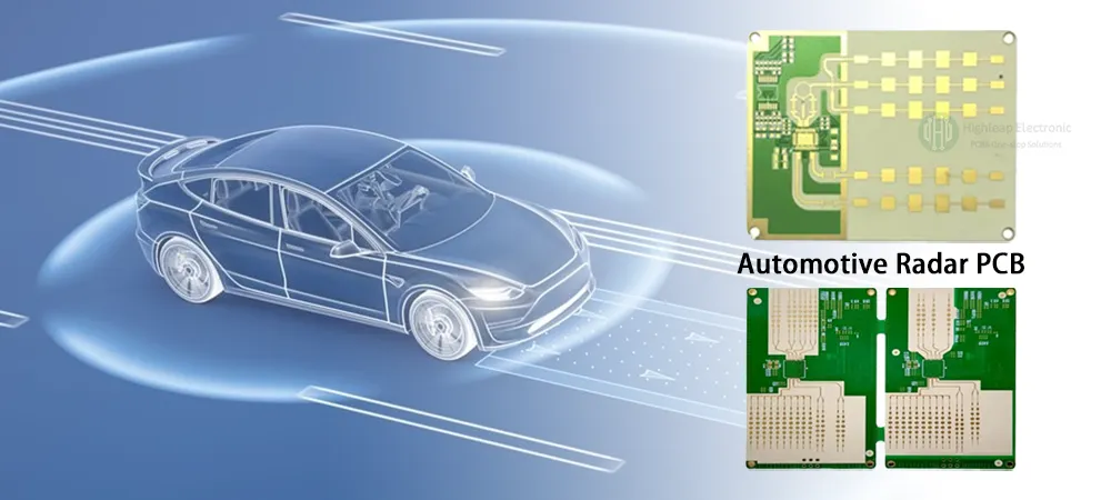
Automotive Safety and Autonomous Driving
The automotive industry relies on 24GHz and 77GHz radar for Adaptive Cruise Control (ACC) and Automatic Emergency Braking (AEB). Rogers RO3003 laminates provide the stability required for these sensors to operate reliably in a wide range of temperatures, from -40°C to +125°C, ensuring consistent obstacle detection.
Aerospace and Defense Systems
In aerospace, Rogers PCBs are used in phased-array radars and electronic warfare (EW) systems. The RT/duroid® series is particularly valued for its low outgassing properties, which is a critical requirement for hardware operating in the vacuum of space.
Medical Instrumentation
High-frequency Rogers laminates are used in RF ablation tools and high-resolution medical imaging equipment. The low-noise floor provided by these materials allows for more precise signal capture, leading to better diagnostic accuracy.
Manufacturing Excellence: Challenges and Best Practices
Fabricating a board with Rogers materials requires specialized equipment and processes that differ significantly from standard FR-4 production.
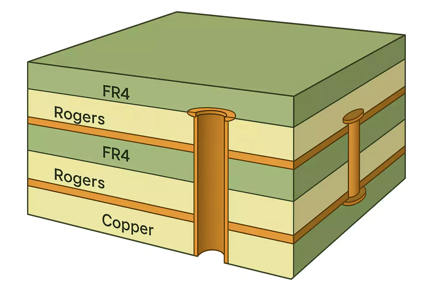
Hybrid PCB Stackups
One of the most cost-effective Rogers PCB applications is the Hybrid Stackup. In this configuration, Rogers laminates are used only for the critical high-frequency layers, while standard FR-4 is used for the inner layers (power and ground). This requires careful calculation of the "Press-Out" thickness and thermal expansion compatibility between the two disparate materials.
Surface Preparation and Hole Cleaning
PTFE-based Rogers materials are chemically inert, which makes copper plating difficult. Manufacturers must use specialized plasma etching or sodium-based chemical treatments to "roughen" the hole walls before plating can occur. This ensures a strong mechanical bond for the copper in the through-holes.
Drilling Precision
The ceramic filler in many Rogers materials is abrasive and can wear out drill bits rapidly. Furthermore, the softness of PTFE can lead to "entry/exit burrs" and "smearing." Precise control over drill speed, feed rate, and the number of hits per bit is essential for quality control.
Designing for the Future: Critical Considerations
When designing a Rogers PCB application, engineers must look beyond just the datasheet.
-
Copper Foil Selection: Standard electrodeposited (ED) copper may be too rough for very high frequencies, causing "skin effect" losses. Rolled-annealed (RA) or Low-Profile (LoPro) copper is often required.
-
Surface Finish: For RF designs, the surface finish can significantly impact loss. While ENIG (Electroless Nickel Immersion Gold) is standard, Immersion Silver or ENEPIG may be preferred at frequencies above 20GHz to avoid the "Nickel effect" on signal loss.
-
Moisture Sensitivty: While Rogers materials absorb very little moisture, the small amount they do absorb can shift the Dk of the board. Proper baking and sealing protocols during manufacturing are vital.
Conclusion: The Competitive Edge of Rogers Materials
The demand for faster, smaller, and more reliable electronics shows no signs of slowing down. Whether you are exploring advanced Rogers PCB materials for high-frequency applications to solve a specific signal integrity hurdle or building the next wave of mobile connectivity by integrating Rogers PCB materials in 5G infrastructure, these substrates provide the physical foundation for innovation.
By understanding the synergy between material science and RF engineering, manufacturers can produce PCBs that not only meet today’s standards but are ready for the 6G and autonomous challenges of tomorrow.
FAQs
Q1: Can Rogers materials be processed on standard PCB assembly lines?
A1: Yes, most Rogers materials (especially the RO4000 series) are designed to be "FR-4 process compatible." They can be assembled using standard lead-free solder reflow profiles. However, PTFE-based materials like the RO3000 series may require specialized handling to prevent deformation.
Q2: Why is the Dielectric Constant (Dk) so important for RF applications?
A2: Dk determines the speed at which electrical signals travel through the substrate. If the Dk is inconsistent, the signal phase will shift, leading to timing errors and interference. Rogers materials provide the tight Dk tolerance necessary for phase-sensitive applications like radar and high-speed data.
Q3: What is the most cost-effective way to use Rogers materials?
A3: The most cost-effective approach is the Hybrid PCB. By using Rogers only for the layers that carry high-frequency signals and FR-4 for everything else, you can achieve the required performance at a fraction of the cost of a full-Rogers multilayer board.
Q4: How do I choose between the Rogers 3000 and 4000 series?
A4: Generally, the RO4000 series is preferred for applications where ease of manufacturing and cost are important (like 5G base stations). The RO3000 series (PTFE-based) is chosen for the highest-frequency applications (like 77GHz automotive radar) where the absolute lowest loss is mandatory.


