Introduction
Advanced Driver Assistance Systems (ADAS) represent a cornerstone of modern automotive technology, integrating sensors, processors, and interfaces to enhance vehicle safety and performance. Printed circuit boards (PCBs) serve as the foundational platform for these systems, enabling the seamless operation of electronic devices that process vast amounts of real-time data. As advancements in automotive electronics accelerate, PCBs must evolve to support higher speeds, greater reliability, and compact designs. This article explores how PCBs underpin ADAS functionality, from sensor fusion in radar and camera modules to user interfaces featuring touch screens and voice commands. Electrical engineers designing these systems face unique challenges in balancing signal integrity, thermal management, and environmental robustness. Understanding these PCB advancements ensures optimal system performance in demanding automotive environments.
The Critical Role of PCBs in ADAS
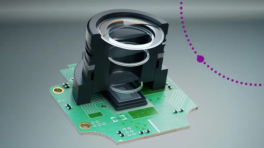
PCBs in ADAS systems interconnect diverse components such as microcontrollers, power management ICs, and high-speed transceivers, forming the backbone of electronic control units (ECUs). These boards handle data from lidar, ultrasonic sensors, and cameras, fusing inputs for features like adaptive cruise control and lane-keeping assistance. In infotainment clusters, PCBs support electronic devices that drive touch screens and voice command processors, providing intuitive human-machine interfaces. The integration of these elements demands PCBs capable of withstanding vibration, temperature fluctuations, and electromagnetic interference common in vehicles. Reliability directly impacts safety, as failures could compromise critical functions. Thus, PCB design plays a pivotal role in realizing the full potential of ADAS advancements in automotive applications.
Key Advancements in Automotive PCBs for ADAS
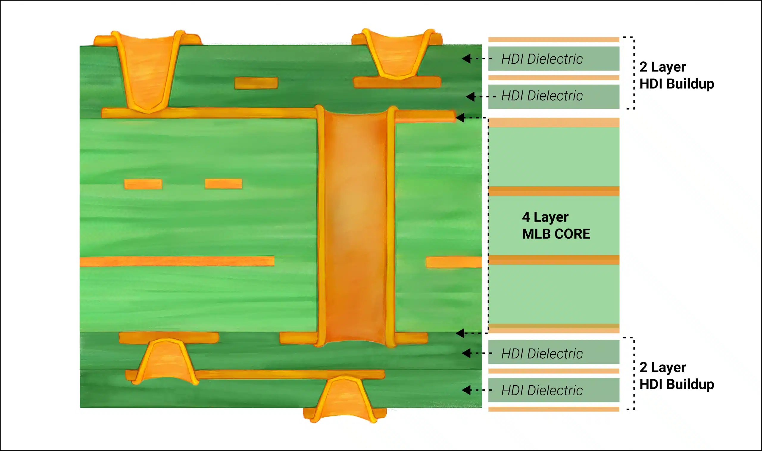
Recent advancements in automotive PCBs focus on high-density interconnect (HDI) structures and advanced materials to accommodate the growing complexity of ADAS. Multi-layer boards with microvias and blind/buried vias enable tighter component spacing, crucial for compact sensor modules. Low-loss dielectrics with controlled impedance support gigabit data rates in radar systems operating at millimeter-wave frequencies. Embedded passives and actives reduce board real estate while improving signal integrity. Thermal vias and metal-core substrates address heat dissipation from high-power processors in ECUs. These innovations allow electronic devices to process sensor data faster, enhancing ADAS responsiveness.
High-frequency laminates minimize dielectric losses, ensuring clean signal transmission for camera and lidar interfaces. Flex-rigid hybrids facilitate integration in curved dashboard assemblies, supporting seamless connectivity. Automotive-grade coatings enhance corrosion resistance against humidity and salt exposure. These PCB evolutions align with the push toward Level 3 and higher autonomy, where real-time computing demands exceed traditional designs.
Integrating Touch Screens and Voice Commands in ADAS Interfaces
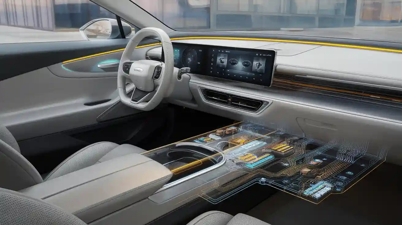
Touch screens in ADAS-enabled dashboards rely on PCBs to interface capacitive sensors, display drivers, and touch controllers, delivering responsive multi-touch capabilities. These boards incorporate fine-pitch traces to connect ITO layers on glass overlays, minimizing latency in gesture recognition. Voice command systems integrate audio codecs, DSPs, and wake-word detection chips on the same PCB, enabling hands-free operation. Advancements in automotive electronics allow these PCBs to fuse voice inputs with ADAS alerts, such as navigation prompts or collision warnings. Noise-cancellation circuits on the board filter engine sounds, improving accuracy. Power-efficient designs extend battery life in electric vehicles while maintaining low electromagnetic emissions.
PCBs for these interfaces often feature shielded layers to prevent crosstalk between high-speed display signals and audio paths. Surface-mount components like MEMS microphones mount directly, reducing assembly complexity. Integration with central gateways allows voice commands to trigger ADAS functions, like adjusting cruise control. Electrical engineers must optimize stackups for mixed-signal environments, ensuring analog voice paths remain isolated from digital touch data. These capabilities represent significant advancements in automotive user experiences.
Technical Challenges in ADAS PCB Design
Designing PCBs for ADAS involves overcoming signal integrity issues at high data rates, where reflections and crosstalk degrade performance. Power delivery networks must supply stable voltages to processors handling terabytes of sensor data daily. Thermal cycling from -40°C to 125°C induces warpage, demanding robust material selections. EMI compliance requires ground planes and stitching vias to contain emissions from switching regulators. Vibration resistance calls for underfill epoxies and conformal coatings on components. Engineers address these through simulation-driven layouts, verifying impedance with time-domain reflectometry.
Material CTE mismatch between copper and substrates causes reliability failures under thermal stress. High-layer counts amplify via stub effects, necessitating back-drilling. For touch screens and voice commands, grounding strategies prevent false triggers from electrical noise. Adherence to standards like IPC-6012DS ensures qualification for automotive environments, specifying criteria for plating thickness and hole wall integrity. These challenges drive iterative prototyping and testing.
Best Practices for ADAS PCB Development
Start with a controlled impedance stackup, targeting 50 ohms for single-ended and 100 ohms for differential pairs in sensor interfaces. Select high-Tg FR-4 or polyimide for thermal stability, verifying via DSC analysis. Route high-speed traces on inner layers away from edges to minimize radiation. Implement decap placement near ICs for transient suppression, following derating guidelines. For assembly, follow IPC-A-610 Class 3 criteria to inspect solder joints under magnification. Bake components per J-STD-020 moisture sensitivity levels before reflow, preventing popcorning.
Incorporate test points for in-circuit verification and boundary scan for production yields. Use via-in-pad for density but tent them to avoid solder wicking. Simulate crosstalk with 3D solvers, iterating until eye diagrams meet margins. For touch screen and voice command boards, dedicate ground pours around analog sections. These practices enhance yield and longevity in field deployments.
Conclusion
PCBs form the essential nexus for ADAS, bridging sensors, processors, and interfaces amid rapid advancements in automotive electronics. From high-speed HDI for radar to mixed-signal designs for touch screens and voice commands, these boards demand precision engineering. Overcoming thermal, mechanical, and electrical hurdles through standards-compliant practices ensures system reliability. Electrical engineers leveraging these insights can deliver robust solutions that advance vehicle safety and autonomy. As ADAS evolves, PCB innovation will remain central to automotive progress.
FAQs
Q1: What role do advancements in automotive PCBs play in ADAS sensor integration?
A1: PCBs enable fusion of radar, lidar, and camera data through high-layer HDI and low-loss materials, supporting gigabit Ethernet and PCIe interfaces. Controlled impedance stackups maintain signal integrity at high frequencies. Thermal management via metal cores handles processor heat. These features allow real-time processing critical for safety functions, aligning with reliability standards.
Q2: How do PCBs support touch screen and voice command features in electronic devices for ADAS?
A2: PCBs integrate capacitive controllers, display drivers, and audio DSPs on compact layouts, using shielded traces to isolate signals. Fine-pitch routing connects touch sensors while ground planes reduce noise for voice recognition. Power-efficient designs minimize EMI. This enables seamless interaction, enhancing driver focus during ADAS operation.
Q3: What standards guide PCB quality for ADAS applications?
A3: IPC-6012DS outlines qualification for automotive rigid boards, emphasizing plating and cleanliness. IPC-A-610 Class 3 ensures high-reliability assembly inspections. J-STD-020 manages component moisture sensitivity. These prevent failures in harsh environments, supporting ADAS dependability.
Q4: Why is thermal management crucial in ADAS PCBs?
A4: High-power ECUs and processors generate heat, risking performance degradation. Vias, heat sinks, and high-Tg materials dissipate it effectively. This maintains junction temperatures within limits, preserving electronic devices like those for touch screens and voice commands. Proper design extends lifespan in automotive conditions.
References
IPC-6012DS - Qualification and Performance Specification for Rigid Printed Boards, Automotive Addendum. IPC.
IPC-A-610F - Acceptability of Electronic Assemblies. IPC, 2014.
J-STD-020E - Moisture/Reflow Sensitivity Classification for Nonhermetic Surface Mount Devices. JEDEC, 2014.


