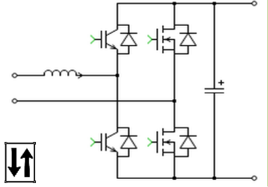
Overview
This article describes an electric bicycle (e-bike) battery level indicator, low-voltage alarm and control circuit. Specifically: when a fully charged battery is connected, the power indicator lights and the three level LEDs are all on. As the battery discharges, the indicators show two LEDs, then one, then none. When the battery voltage falls below 30 V the alarm LED turns on and the drive is disabled.
12 V Precision Regulator and Supply
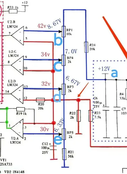
The 12 V precision regulator is built from DB235 and TL431 with its input supplied by the battery (BATT). The regulator output is filtered by C6 and C7 to produce a smooth 12 V at point a (marked in blue). This 12 V rail supplies the LM324 operational amplifier and subsequent circuitry. When the 12 V supply is present, LED4 is driven through R33 to ground and LED4 lights.
Voltage Dividers and Comparator Reference Levels
Point a (marked in blue) at 12 V is divided through R24, RP1, RP4, RP3, RP5 and R21 in series. The divided voltages feed the inverting inputs of the LM324 internal op amps U2:B, U2:C, U2:D and U2:A at pins 6, 9, 13 and 2 respectively. Those inverting input reference voltages are 8.67 V, 7.00 V, 6.67 V and 6.33 V.
The battery voltage is divided by resistors R22 and R23 and fed to LM324 pins 5, 10, 12 and 3. The voltages at these four pins scale with the battery according to 2/(2+7.5) * V_batt.
Operating States at Given Battery Voltages
1. When the battery voltage is 42 V, the voltages at LM324 pins 5, 10, 12 and 3 are all 2/(2+7.5)*42 = 8.84 V. These are the non-inverting inputs of U2:B, U2:C, U2:D and U2:A. Since each non-inverting input is greater than its corresponding inverting input, the outputs at LM324 pins 7, 8, 14 and 1 go high (about 12 V). LED1, LED2 and LED3 all light. The high level at pin 1 prevents LED5 (alarm) from lighting and keeps transistor VT6 off.
2. When the battery voltage is 34 V, the voltages at pins 5, 10, 12 and 3 are 2/(2+7.5)*34 = 7.16 V. For U2:C, U2:D and U2:A the non-inverting inputs remain higher than the inverting inputs, so outputs at pins 8, 14 and 1 stay high and LED1 and LED2 remain lit. For U2:B the non-inverting input is lower than its inverting input (7.16 < 8.67), so the output at pin 7 goes low (about 0 V) and LED3 is off. The low level does not enable LED5 and VT6 remains off.
3. When the battery voltage is 32 V, the voltages at pins 5, 10, 12 and 3 are 2/(2+7.5)*32 = 6.74 V. For U2:D and U2:A the non-inverting inputs are still above their inverting inputs, so outputs at pins 14 and 1 go high and LED1 remains lit. For U2:B and U2:C the non-inverting inputs are below their inverting inputs (6.74 < 8.67 and 6.74 < 7.00), so outputs at pins 7 and 8 go low and LED3 and LED2 are off. The high at pin 1 still prevents LED5 from lighting and VT6 remains off.
4. When the battery voltage falls to 30 V, the voltages at pins 5, 10, 12 and 3 are 2/(2+7.5)*30 = 6.32 V. All four non-inverting inputs are now below their inverting inputs, so outputs at LM324 pins 7, 8, 14 and 1 go low (about 0 V). LED1, LED2 and LED3 are all off. The low at pin 1 allows current through the LED5 and R14 branch, so LED5 (alarm) lights. At the same time VT6 becomes forward biased via R27, turning VT6 on. The 12 V is then passed through VT6 and R29 to TL494 pin 4. Pin 4 of TL494 is the dead-time control input and must not exceed 3.3 V; if it does, TL494 enters protection and pin 8 produces no output. As a result, the battery is prevented from powering the e-bike drive motor and the vehicle is disabled.