Introduction
Where is my charger? This is one of the most common questions today. Falling battery costs and improved performance, especially for lithium-based cells, have driven steady growth in battery-powered storage and portable devices. Supercapacitors are also increasingly used because of their unique properties.
Lead-acid batteries are a 150-year-old technology and remain widely used in automotive, mobility scooters, scooters, golf carts, and uninterruptible power supply systems. Once energy is depleted, these storage devices must be recharged. Global charger IC shipments were 1.16 billion units in 2019 and are expected to reach 1.72 billion units by 2024, a healthy 8.6% annual growth rate. Revenues were $518.1 billion and $735.4 billion respectively, with a 7.3% compound annual growth rate. Figure 1 shows this trend.
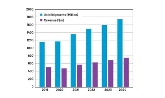
Figure 1. Global charging IC market
Demand for more power, longer range, or extended runtime has pushed the voltage used by storage devices higher. Battery stacks used in robots, drones, power tools, and many other systems have grown from one or two cells to multiple cells, up to 12 cells. A 12-cell lithium-ion stack can provide up to 50.4 V. At the same current rating, a 12-cell stack yields 12 times the runtime of a single cell. Alternatively, paralleling 12 cells increases current 12-fold, which raises conduction losses and is generally undesirable.
Industrial systems that use 24 V backup batteries for emergency lighting, UPS backup, or high-voltage AC systems may see transient peak voltages up to 60 V according to IEC 61131-2 and IEC 60664-1 standards. In either case, charger solutions must support higher battery voltages and withstand higher input voltages during transient events.
Charger Basics
Chargers use many topologies. Linear chargers reduce the voltage difference between the source and the battery through a power switch; they are the least efficient because the power switch dissipates significant power when the voltage difference is large. Boost chargers step source voltage up to the battery voltage and require the source voltage to be lower than the battery. Buck chargers step source voltage down and require the source to be higher than the battery. Buck-boost chargers can charge from sources higher or lower than the battery, but require four power switches (a buck topology typically needs two) and are generally less efficient.
Synchronous-rectified buck chargers offer the highest efficiency and are the focus here. Figure 2 shows a generic synchronous-rectified buck charger. Most buck chargers today operate at relatively low voltages; many are rated for only 28 V input, some for 40 V. With +/-10% input voltage tolerance and a 2 V buck voltage drop, a charger rated at 28 V can at most charge a 5S lithium-ion stack. This article examines a family of 60 V input charger ICs that support higher battery voltages—up to 52 V (12-cell lithium-ion stacks)—and can withstand 65 V input transients.
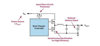
Figure 2. Generic synchronous-rectified buck charger
Chargers should have low standby current to save energy. Energy Star specifies standby power of 30 mW or less for mobile chargers and other small chargers to receive a top rating. One-star ratings apply to chargers with 300 mW or higher standby power. Energy Star aims to reduce the power consumed by personal chargers that remain connected to the mains when not in use. At any given time, there are over a billion such chargers connected worldwide.
Although lead-acid batteries, lithium-ion batteries, and supercapacitors are all storage devices, their charge/discharge characteristics differ significantly. The following sections examine those characteristics and discuss suitable charging solutions. A good battery charger provides reliable battery performance and durability, especially under adverse conditions.
Lead-Acid Battery Chargers
Lead-acid batteries were invented in 1859 and are still widely used for automotive, mobility, scooters, electric bicycles, golf carts, and UPS systems.
Lead-acid batteries must be charged slowly. Typical charge times are 8 to 16 hours. Batteries should be stored in a charged state, and periodic full saturation charges are important to prevent sulfation. A common approach is to charge to about 70% in roughly 8 hours, then complete the final top-up charge over another 8 hours. Occasional full saturation charges prevent sulfation; float charging for extended periods does not cause damage.
Choosing an appropriate charge voltage limit is critical. High voltage (above 2.45 V per cell) yields good performance but shortens life due to positive plate grid corrosion. Low voltage limits cause negative plate sulfation. Temperature also affects battery voltage; the typical temperature coefficient is -5 mV/°C per cell (approximately 0.028 V per cell per 10°F). Good chargers must compensate for this temperature coefficient to avoid overcharging at high temperatures or undercharging at low temperatures.
For example, the MAX17702 is a complete lead-acid battery charger controller designed for a 4.5 V to 60 V input range. The device provides a high-efficiency (>97%), high-voltage, synchronous buck solution for charging 12 V, 24 V, and 48 V lead-acid battery packs. Figures 3 and 4a/4b show the charging cycle and charging efficiency for this controller.
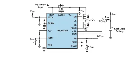
Figure 3. High-voltage lead-acid battery charger controller
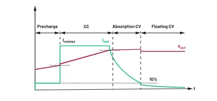
Figure 4a. MAX17702 lead-acid charging cycle
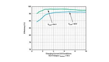
Figure 4b. MAX17702 charging efficiency
Lead-acid batteries have low energy density and are not suitable for portable devices, which typically use lithium batteries.
Lithium-Ion Battery Chargers
Lithium-ion batteries are used widely in portable applications, heavy industry, electric drive systems, and satellites due to their light weight and high energy density.
Lithium-ion batteries require little maintenance. They have no memory effect and do not need deliberate full discharge to maintain performance. However, protection circuits are required both inside battery packs and in chargers to prevent short circuits, overcharge, thermal runaway, and overdischarge. If a lithium-ion cell remains below about 1.5 V per cell for a week or longer, dendritic growth can produce safety issues.
To prevent overdischarge, built-in protection circuits put the battery into a sleep state when stored in a discharged condition; when self-discharge drops the voltage below a cutoff, the pack may appear unusable to a conventional charger and is often discarded. Advanced lithium-ion chargers include a wake or "precharge" function to revive deeply discharged packs. In precharge mode, the charger applies a small current to raise the cell voltage safely to about 2.2 V to 2.9 V per cell to reactivate the protection circuit, then proceeds to normal charging.
During normal charging, lithium-ion chargers operate in constant-current/constant-voltage (CC/CV) mode. The charger supplies a constant current until the battery voltage reaches the set limit, then holds the voltage while current tapers as the battery reaches saturation. Charging terminates when the current falls below a defined tail-current threshold. Each battery chemistry requires specific low-current thresholds.
Lithium-ion cells should be kept cool during charging and cannot accept excessive overcharge. Monitoring cell temperature and charge voltage is essential for safety and battery health. Good chargers include these protections.
Figure 5 shows an advanced lithium-ion charger example. The MAX17703 is a high-efficiency, high-voltage, synchronous buck charger controller designed for a 4.5 V to 60 V input range. It provides a complete charging solution for up to 12-cell lithium-ion stacks.
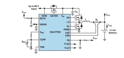
Figure 5. Advanced high-voltage lithium-ion charger circuit
The device provides accurate CC/CV charge current and voltage regulation to +/-4% and +/-1% respectively. When the charge current falls to the tail-current threshold, the charger enters a top-off mode; after the timer expires, charging stops. The charger restarts a charge cycle when the output voltage falls below the charge threshold. This feature helps keep batteries topped up when left on a charger for extended periods without wasting much power and meets Energy Star requirements. The device can detect and precondition deeply discharged batteries, using precharge to wake them. Additional protections include battery temperature monitoring to permit charging only within a specified temperature range and input short-circuit protection to prevent battery discharge back into the input. Figure 6 shows the MAX17703 charging cycle.
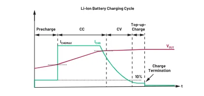
Figure 6. MAX17703 lithium-ion battery charging cycle
Supercapacitor Chargers
Supercapacitors have several advantages compared with batteries and are increasingly used across applications. They operate on electrostatic principles without chemical reactions, avoiding many lifetime issues associated with chemical storage. Their high durability supports millions of charge/discharge cycles and lifetimes up to about 20 years, an order of magnitude greater than many batteries. Low internal resistance enables rapid charge and discharge in seconds. Moderate long-term charge retention and fast response make supercapacitors suitable for applications requiring rapid cycling. Supercapacitors can also be used in parallel with batteries to supply instantaneous peak power during load transitions.
Fast charge/discharge cycles require chargers that can handle high currents, operate smoothly in constant-current (CC) mode during charge from 0 V, and switch to constant-voltage (CV) mode when the final voltage is reached. In high-voltage applications, many supercapacitors are placed in series, so the charger must manage high input and output voltages.
The MAX17701 is a high-efficiency, high-voltage, synchronous buck supercapacitor charger controller designed for high-current charging with a 4.5 V to 60 V input range. Output voltage is programmable from 1.25 V up to VDCIN - 4 V. The device uses external N-MOSFETs to provide an input-side "OR-ing" function to prevent supercapacitor discharge back to the input. Figure 8 shows a simple high-current charge curve.
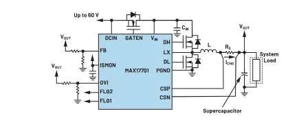
Figure 7. High-voltage, high-current supercapacitor charger
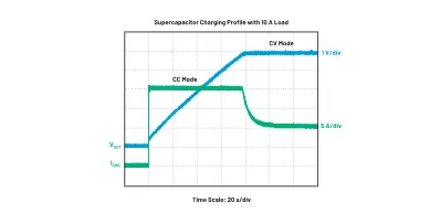
Figure 8. MAX17701 supercapacitor charging curve
Conclusion
Battery-powered storage and portable device usage continue to grow. Demand for more power and longer runtime drives higher battery stack voltages. Industrial systems using 24 V batteries can experience 60 V peak transients. Traditional charger solutions often assume 28 V inputs. High-voltage synchronous buck charger topologies enable charger solutions that support higher battery stack voltages and improved charging efficiency.
Lead-acid batteries, lithium-based batteries, and supercapacitors have distinct charge and discharge behaviors and require dedicated charger designs for optimal performance. Advanced chargers include protections to preserve battery performance and durability, particularly under adverse charging conditions. These features are implemented in modern charger solutions.