1. GPS Basics
GPS, short for Global Positioning System, is widely used in everyday applications. Most modern smartphones include GPS positioning. GPS is an American global positioning system. Other systems such as BeiDou also exist, but GPS was developed earlier, so it is often used as a starting point for study.
The GPS system is divided into three main segments: ground control, satellites, and receivers.
- Ground control monitors the system. Ground stations receive and measure satellite signals, compute satellite orbits, and upload orbital information so satellites can broadcast it.
- Satellites broadcast signals toward Earth in a continuous manner.
- Receivers obtain satellite signals, extract satellite ephemeris and timing information, and compute their own position.
Ground control and satellites are operated by the United States; end users control only the receiver.
The basic positioning principle is simple and can be explained with basic geometry. Model the receiver as point X and three satellites as points A, B, C. If the distances from the receiver to the three satellites are rx, ry, rz, then spheres centered at the satellite positions with radii rx, ry, rz intersect at two points. The correct receiver location is the point near Earth's surface, which can be selected based on context.
Distances rx, ry, rz are obtained from the relationship distance = speed × time. Satellite signals travel at the speed of light, so measuring the signal travel time gives range. The reception time is known to the receiver, and the transmit time is encoded in the signal, so travel time equals reception time minus transmit time. However, receiver clocks are not synchronized with satellite clocks, introducing a clock bias unknown. Therefore a fourth satellite is needed: with four satellites there are four equations to solve for four unknowns (three coordinates plus clock bias).
Expressed as equations: let the receiver coordinates be (x, y, z), satellite n coordinates be (xn, yn, zn) for n = 1,2,3,4, satellite-to-receiver distances rn, c the speed of light, and δt the clock bias. The standard pseudorange equations are used to solve for position and clock bias.
2. GPS Time
GPS positioning uses a clock bias term introduced earlier. Time is relative: two clocks may disagree, which causes errors when time is used to compute distance. To avoid large errors, GPS time is used as a unified time reference.
Multiple civil time systems exist. Examples include Universal Time (UT) based on Earth's rotation, International Atomic Time (TAI) based on atomic clocks, and Coordinated Universal Time (UTC) which is a compromise used as civil standard time in most countries. GPS, however, defines its own continuous time scale, GPS Time (GPST).
Key points about GPS Time:
- GPS Time is continuous.
- GPST is represented by a week number and seconds of the week.
- Second duration in GPST is derived from observations of atomic clocks at ground stations and on satellites.
- GPST epoch is synchronized to 00:00:00 on January 6, 1980 (UTC).
- GPST lags International Atomic Time (TAI) by 19 seconds plus a subsecond offset. The US maintains satellite clock offsets to keep the subsecond offset under 1 microsecond, typically within a few hundred nanoseconds.
Each GPS satellite maintains its own onboard satellite time, running on its local clock. Ground control ensures the difference between satellite time and GPS Time remains small (within about 1 microsecond). Time-related fields in the navigation message that reference satellite time appear in telemetry words (TLW) and handover words (HOW); other navigation data are referenced to GPS Time.
The difference between GPS Time and UTC is provided in the navigation message (see navigation message subframe 4, page 18). Ground control is responsible for updating these parameters at least every six days to limit accuracy degradation. Satellite clock offset parameters are broadcast in navigation message subframe 1.
With these relationships among satellite time, GPS Time, and UTC, the receiver time remains an independent variable, so a clock bias term must be solved along with position. Once time relationships and error bounds are known, time-based ranges can be computed and used for positioning.
3. Coordinate Systems
Positioning requires coordinate systems. Coordinates are always relative to a chosen reference frame. Coordinate systems fall into two broad categories: inertial frames and non-inertial frames. Inertial frames are those at rest or in uniform linear motion; others are non-inertial.
Before listing coordinate systems used by GPS, some basic concepts:
- Poles: the intersection points of Earth's rotation axis with the Earth's surface, called the North Pole and South Pole.
- Equator plane: the plane through Earth's center perpendicular to the rotation axis.
- Equator: the great circle formed by the intersection of the equator plane and Earth's surface.
- Celestial sphere: a conceptual sphere centered on Earth's center for projecting celestial objects along sightlines.
- Ecliptic: the apparent path of the Sun on the celestial sphere, defined by the plane of Earth's orbit around the Sun.
- Obliquity of the ecliptic: the angle between the ecliptic and equatorial planes, about 23.5°.
- Vernal equinox: one of the two intersections of ecliptic and equator where the Sun moves from south to north across the equator.
- Precession: long-term movement of Earth's rotation axis causing the vernal equinox to shift along the ecliptic, with a period around 25,800 years.
- Nutation: shorter-period variations in Earth's rotation axis due to lunar motion, with an 18.6-year component.
- Polar motion: slow wandering of Earth's rotation axis relative to Earth's crust.
- Meridian plane: any plane that contains Earth's rotation axis.
- Prime meridian plane: the plane through the Greenwich Observatory and Earth's rotation axis used as the reference for longitude.
With these concepts, the five major coordinate systems relevant to GPS are:
Earth-Centered Inertial (ECI)
The ECI frame is an inertial frame in the solar system that does not rotate with Earth and is not affected by precession or nutation. Origin at Earth's center. The X-axis lies in the equatorial plane pointing to the vernal equinox at a specific epoch. The Z-axis points to the mean north pole at that epoch. The Y-axis completes a right-handed system. Different epochs yield different ECI frames; the common standard is the J2000 epoch, referenced to the vernal equinox of year 2000.
Earth-Centered Earth-Fixed (ECEF)
The ECEF frame is fixed to Earth and rotates with it. A fixed point on the Earth has fixed ECEF coordinates. Origin at Earth's center. The X-axis points to the intersection of the reference meridian and equator. The Z-axis aligns with Earth's rotation axis toward the north pole. The Y-axis completes a right-handed system. Because of polar motion, an agreed conventional pole is used as reference based on the average pole position from 1900 to 1905.
Geodetic Coordinates: Longitude, Latitude, Altitude (LLA)
LLA is also Earth-fixed with origin at Earth's center and is defined relative to a reference ellipsoid. Geodetic latitude φ is the angle between the normal to the reference ellipsoid at the point and the equatorial plane, ranging from -90° to +90° (positive in the Northern Hemisphere). Longitude λ is the angle between the meridian plane of the point and the prime meridian, ranging from -180° to +180°. Height h is the distance along the ellipsoid normal from the reference ellipsoid to the point, positive outside the ellipsoid and negative inside.
Local Tangent Plane: East-North-Up (ENU)
Also called the East-North-Up system, centered at the observer station. Axes point east, north, and up respectively. ENU is useful for describing satellite vectors relative to a local observer and for computing elevation and azimuth angles.
WGS-84
World Geodetic System 1984 (WGS-84) is an Earth-centered, Earth-fixed Cartesian coordinate system widely used for GPS. Origin at Earth's center. The Z-axis points to the conventional terrestrial pole defined in 1984. The X-axis points to the intersection of the prime meridian and the CTP equator. The navigation broadcast ephemerides are referenced to WGS-84.
Coordinate Transformations
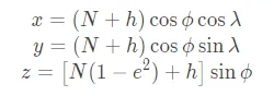
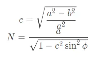
Common conversions include LLA → ECEF and ECEF → LLA. The LLA to ECEF equations involve ellipsoid eccentricity e and the prime vertical radius of curvature N. If the semi-major axis is a and semi-minor axis is b, then standard relations are used to compute e and N.
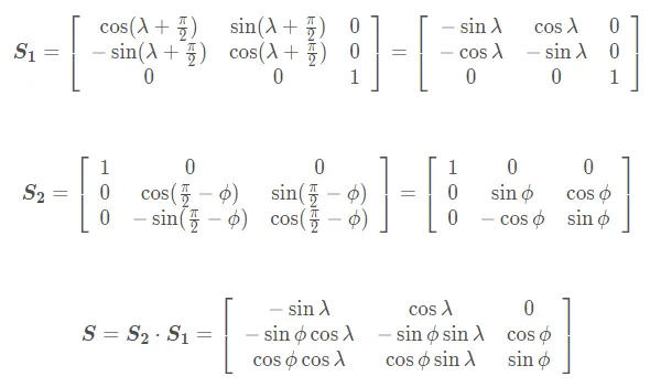
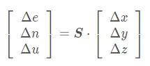
For ECEF → ENU and ENU → ECEF conversions: the user-to-satellite observation vector [Δx Δy Δz]T (satellite position minus user position) can be transformed to ENU by rotating ECEF coordinates: first rotate about the Z-axis by λ+90°, then rotate about the new X-axis by 90°-φ. This yields the transformation matrix:
The user-to-satellite vector in ENU coordinates is:
From this vector, the satellite elevation angle θ and azimuth α relative to the user can be computed. Elevation θ is the angle above the horizontal:
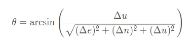
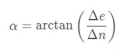
Azimuth α is the bearing of the horizontal projection of the observation vector measured clockwise from north:
4. GPS Signal Structure
GPS signal structure has three layers: carrier, pseudorandom code (PRN), and data message.
Carrier
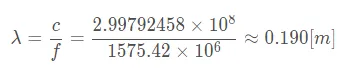
The carrier is the physical waveform on which pseudorandom code and navigation data are modulated. GPS uses two main carrier frequencies: L1 at 1575.42 MHz and L2 at 1227.60 MHz. Most civilian receivers use the L1 carrier. From frequency, the L1 wavelength λ can be computed as λ = c / f.
Pseudorandom Codes
Pseudorandom codes serve two main purposes: multiple access and ranging. GPS is a code-division multiple access (CDMA) spread-spectrum system. Two main code types exist: the publicly available C/A code and the encrypted P(Y) code. This discussion focuses on the C/A code.
The C/A code is a 1023-chip Gold code. Gold codes are formed by combining two maximum-length sequences and have favorable autocorrelation and cross-correlation properties, which enables satellite separation. Each satellite uses a distinct C/A code.
A C/A code has length 1023 chips and repeats every 1 millisecond, so its chip rate is 1.023 Mcps. A single chip duration is about 1/1.023e6 ≈ 977.5 ns, and multiplied by the speed of light yields a chip length of roughly 293 m. By measuring code phase via correlation, a coarse pseudorange with accuracy on the order of hundreds of meters can be obtained.
For higher accuracy, carrier phase measurements are used. The L1 carrier repeats relative to the C/A code 1575.42 MHz / 1.023 MHz ≈ 1540 times per code period. In theory, carrier phase allows improvement over the 300 m coarse code accuracy by a factor of about 1540, yielding around 0.2 m. In practice, factors such as clock bias, atmospheric delays, and integer ambiguity in carrier phase must be resolved.
Navigation Data
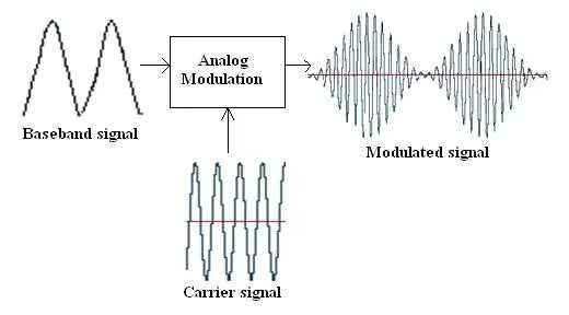
C/A codes are fixed per satellite and cannot carry navigation data by themselves. The GPS navigation message (data bits) is transmitted by modulating the carrier. The data rate is 50 bps, so each data bit lasts 20 ms, corresponding to 20 C/A code epochs. Each data bit is aligned with the first chip of the C/A code epoch.
Before transmission, the navigation data bits are exclusive-ORed with the pseudorandom code. The resulting signal then BPSK-modulates the carrier. The receiver performs the reverse process to recover data and timing.
5. GPS Navigation Message
The navigation message is organized into frames. Each frame contains 1500 bits and is divided into five subframes of 300 bits each. Each subframe has ten words of 30 bits. The most significant bit (MSB) is transmitted first. At 50 bps, one frame requires 30 seconds to transmit.
At the start of each GPS week (midnight between Saturday and Sunday), transmission restarts from subframe 1. Subframes 4 and 5 are transmitted sequentially from page 1 during the frame sequence.
Each subframe begins with a telemetry word (TLW) as the first word, then a handover word (HOW) as the second word, followed by eight data words.
Telemetry Word (TLW)
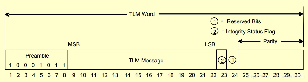
The TLW structure begins with an 8-bit preamble 10001011 used to search for the subframe start. Bits 9 to 22 contain data for protected users and are not used by civilian receivers. Bit 23 is an Integrity Status Flag (ISF) indicating increased integrity assurance when set to 1. Bit 24 is reserved. The final six bits are parity.
Handover Word (HOW)
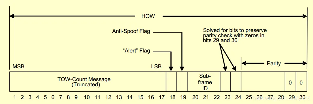
The HOW structure includes bits 1–17 as the truncated Time of Week (TOW), representing the GPS time of the next subframe start in units of 6 seconds. Bit 18 is a warning flag; when set, non-authorized users assume risk using that satellite. Bit 19 is the Anti-Spoof (AS) flag. Bits 20–22 contain the subframe ID (1–5). Bits 23–24 are computed to force the parity bits 29–30 to zero.
Data Words
Data contents differ by subframe.
Subframe 1
Subframe 1 includes:
- Week Number (WN): 10 bits, range 0–1023. Because of the 10-bit limit, the week number rolls over about every 19.6 years. The most recent rollover occurred on April 6.
- Whether P-code and C/A code are present on L2: 2 bits (not discussed here).
- User Range Accuracy (URA): 4 bits indicating predicted ranging accuracy; smaller values correspond to higher expected accuracy.
- Satellite health: 6 bits (1 summary bit plus 5 bits indicating specific issues).
- Issue of Data, Clock (IODC): 10 bits, identifies the epoch of the clock correction parameters.
- Whether L2 P-code carries navigation data: 1 bit (not discussed here).
- Estimated Group Delay Differential (TGD): 8 bits; single-frequency receivers use this to correct ionospheric delay.
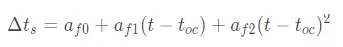
- Satellite clock correction parameters: toc, af0, af1, af2. Satellite clock offset Δts at GPS time t can be computed from these parameters.
Subframes 2 and 3
Subframes 2 and 3 together provide the satellite ephemeris parameters. The ephemeris parameters include:
| Parameter | Bits | Meaning |
|---|---|---|
| toe | 16 | Ephemeris reference time |
| sqrtA | 32 | Square root of the semi-major axis A |
| e | 32 | Orbit eccentricity |
| i0 | 32 | Inclination angle at toe |
| omega | 32 | Argument of perigee |
| M0 | 32 | Mean anomaly at toe |
| Δn | 16 | Mean motion correction |
| i-dot | 14 | Rate of change of inclination |
| Ω | 24 | Rate of right ascension |
| Cuc | 16 | Cosine harmonic correction amplitude for argument of latitude |
| Cus | 16 | Sine harmonic correction amplitude for argument of latitude |
| Crc | 16 | Cosine harmonic correction amplitude for orbit radius |
| Crs | 16 | Sine harmonic correction amplitude for orbit radius |
| Cic | 16 | Cosine harmonic correction amplitude for inclination |
| Cis | 16 | Sine harmonic correction amplitude for inclination |
Additional items in subframes 2 and 3 include:
- Issue of Data, Ephemeris (IODE): 8 bits, indicates whether ephemeris data have changed.
- Curve Fit Interval flag: 1 bit, 0 indicates 4 hours, 1 indicates more than 4 hours.
- Age of Data Offset (AODO): 5-bit unsigned integer multiplied by 900 seconds, used to determine the validity of NMCT entries in subframe 4.
Subframes 4 and 5
Subframes 4 and 5 contain more extensive data split across 25 pages; a complete broadcast requires 25 frames (12.5 minutes). These subframes are not required for initial positioning and typically provide almanac, ionospheric parameters, UTC parameters, and other auxiliary data.
Items included in subframes 4 and 5:
- Data ID and SV ID to indicate the content of the page and the satellite PRN when the page contains ephemeris data.
- Almanac parameters for all satellites.
- Per-satellite almanac entries including toa, sqrtA, eccentricity, inclination, right ascension, argument of perigee, mean anomaly, rate of right ascension, and satellite clock parameters af0 and af1.
| Parameter | Bits | Meaning |
|---|---|---|
| toa | 8 | Almanac reference time |
| sqrtA | 24 | Square root of semi-major axis |
| e | 16 | Eccentricity |
| δi | 16 | Inclination at toa |
| Ω0 | 24 | Right ascension at beginning of the week |
| omega | 24 | Argument of perigee |
| M0 | 24 | Mean anomaly at toa |
| Ω | 16 | Rate of right ascension |
| af0 | 11 | Satellite clock correction parameter |
| af1 | 11 | Satellite clock correction parameter |
Additional information in subframes 4 and 5 includes:
- Satellite health flags for each satellite, appearing both in per-almanac pages and collectively on page 25.
- Anti-spoofing (AS) flags for each satellite in subframe 4 page 25.
- Almanac reference week WNa and toa referenced to it.
- UTC parameters describing the difference between GPS Time and UTC in subframe 4 page 18; these are updated by ground control at least every six days.
| Parameter | Bits | Meaning |
|---|---|---|
| A0 | 32 | Coefficient for computing sub-second time bias |
| A1 | 24 | Coefficient for computing sub-second time bias |
| ΔtLS | 8 | Leap second offset |
| tot | 8 | UTC reference time |
| WNt | 8 | Week number based on UTC |
| WNLSF | 8 | GPS week mod 256 indicating the week of the leap-second date |
| DN | 8 | Day number relative to WNLSF used with WNLSF to indicate leap-second date |
| ΔtLSF | 8 | Replacement value for ΔtLS after a leap second takes effect |
UTC can be computed from GPS Time using parameters broadcast in the navigation message. The relation is tUTC = tE - ΔtUTC, where tE is GPS Time and ΔtUTC is computed from the UTC parameters.
Ionospheric delay correction parameters are broadcast on subframe 4 page 18 as eight 8-bit coefficients α0..α3 and β0..β3 used for single-frequency ionospheric correction.
Special information field: subframe 4 page 17 can contain up to 22 ASCII characters for special messages.
Pseudorange correction values (NMCT) are broadcast on subframe 4 page 13 and include an availability indicator and estimated range deviation (ERD) values for other satellites. ERD entries are used to apply small corrections to pseudoranges; each ERD is 6 bits and the least significant bit corresponds to 0.3 m. The corrected pseudorange PRc is computed from the raw pseudorange RPR and ERD as specified in the navigation message.
Ephemeris vs. Almanac
- Both ephemeris and almanac use Keplerian orbital parameters to describe satellite positions and velocities.
- Ephemeris is valid for a short period, typically 4 hours; almanac is valid for months.
- Ephemeris contains more parameters and correction terms (perturbations); almanac contains fewer parameters and no perturbation corrections.
- Ephemeris provides high accuracy suitable for precise positioning; almanac is lower accuracy and mainly used for satellite search and acquisition.
- Each satellite broadcasts its own ephemeris but also transmits the almanac for all satellites.