In wireless communication systems, channel conditions are critical to signal transmission. Base stations and mobile phones select appropriate resource configurations and transmission methods according to channel conditions. So how does a base station or a phone determine channel conditions?
Consider a real-world example. To ship goods from location A to B and evaluate a freight company's performance, a simple method is to send a single test shipment and assess its transit.
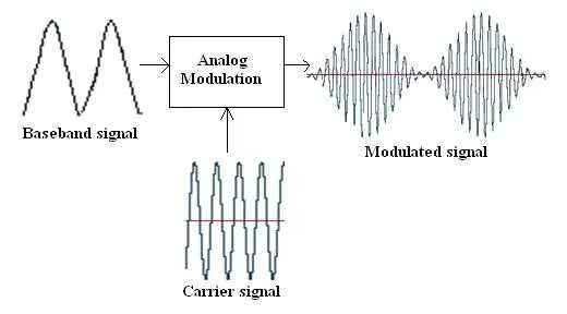
Similarly, to learn channel conditions, one can send a probe signal — a known sequence agreed between transmitter and receiver in terms of content and time-frequency location.
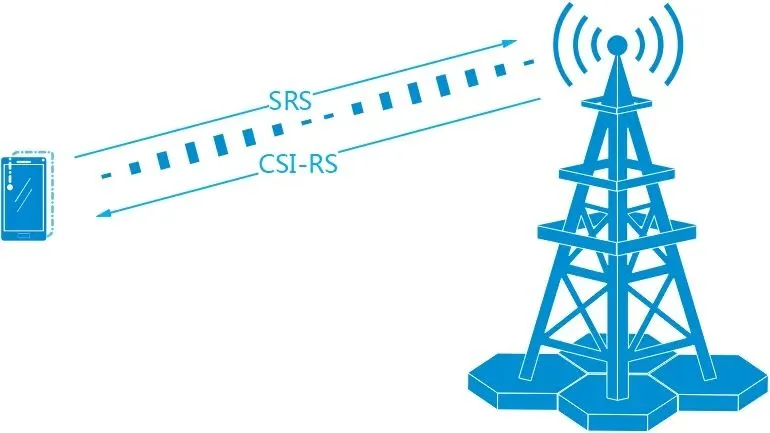
In 5G NR systems, a signal used to probe the uplink channel from the user equipment to the base station is called SRS (Sounding Reference Signal). A signal used to probe the downlink channel from the base station to the user equipment is called CSI-RS (Channel State Information Reference Signal).
This article focuses on SRS.
SRS is a signal configured in the NR protocol to probe the uplink channel.
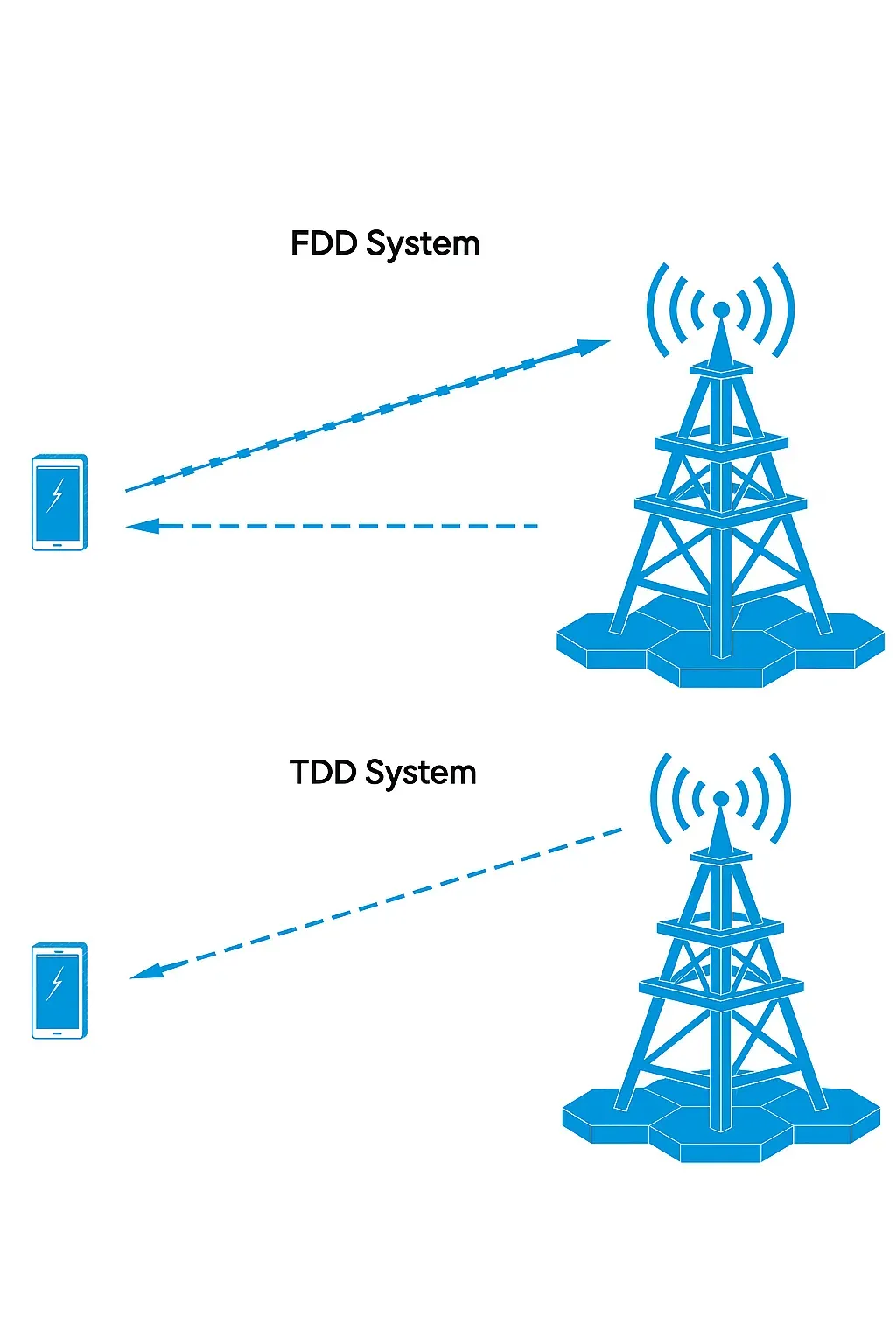
In FDD (Frequency Division Duplex) systems, only the uplink channel state can be measured directly.
In TDD (Time Division Duplex) systems, because of uplink/downlink reciprocity, the uplink measurement can be used to infer downlink conditions. Therefore, in TDD systems, SRS can also be used to measure downlink channel state.
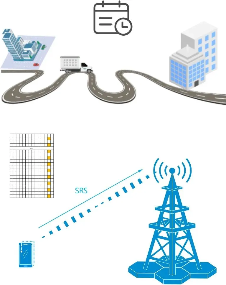
Returning to the shipping analogy, goods do not appear at the destination instantly; the freight company must allocate transport resources, for example assigning a shipment to a scheduled freight vehicle. Similarly, SRS signals are not sent arbitrarily. The protocol defines SRS resource allocation in both time and frequency domains.
Time-domain resources
In the time domain, SRS resources can be configured to occupy 1, 2, or 4 consecutive OFDM symbols among the last 6 OFDM symbols of a slot.
Frequency-domain resources
In the frequency domain, NR supports multiple SRS bandwidth configurations. SRS bandwidth ranges from 4 to 272 RB, in multiples of 4. To enable multi-user SRS resource reuse within the same frequency range, SRS uses a comb structure: the SRS is transmitted every n subcarriers, where n can be 2 or 4. These are referred to as comb-2 and comb-4, respectively.
In the figure below, SRS resource 1 and SRS resource 2 use comb-2, while SRS resource 3 uses comb-4.
SRS transmission types
To probe the uplink channel, one might assume that the UE simply sends SRS periodically. While periodic transmission is one option, the standard defines three SRS transmission types: periodic, semi-persistent, and aperiodic. Each UE can be configured with one of these types for its SRS resources.
Periodic: After receiving a periodic SRS configuration, the UE transmits SRS periodically, with the period expressed in slots.
Semi-persistent: After receiving a semi-persistent SRS configuration, the UE does not transmit immediately. The configuration must be activated via a MAC CE before the UE begins periodic SRS transmission.
Aperiodic: After receiving an aperiodic SRS configuration, the UE transmits SRS only when triggered by downlink DCI or uplink DCI.