Millimeter-wave technology operates in the 30–300 GHz frequency range and pairs effectively with phased-array antennas to overcome high path loss while delivering large bandwidth and fine spatial resolution. These systems are now central to 5G networks, automotive radar, and low-Earth-orbit satellite terminals.
Millimeter-Wave Characteristics and System Requirements
Millimeter waves provide substantially more spectrum than sub-6 GHz bands, enabling multi-gigabit data rates. They also support high-resolution radar because shorter wavelengths reduce diffraction limits. However, free-space path loss increases with frequency according to the Friis equation, and propagation is highly susceptible to blockage by small objects. These factors necessitate directional, high-gain antennas and dense deployment.
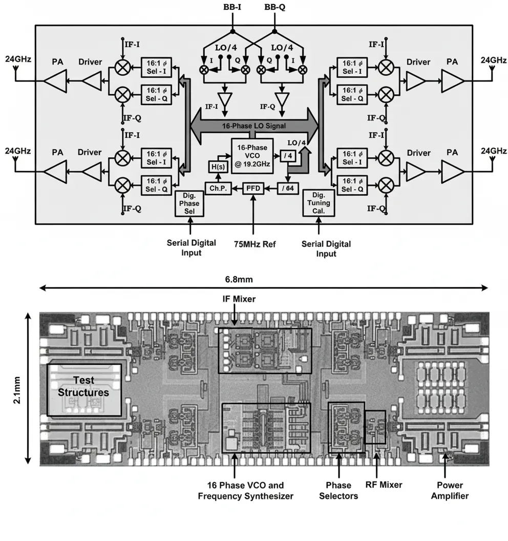
At the circuit level, component dimensions scale with wavelength, allowing compact multi-channel transceivers. A complete 24 GHz four-channel phased-array transmitter, including local oscillator, upconverter, and power amplifiers, can fit on a die measuring only 2.1 mm × 6.8 mm.
Phased-Array Operating Principles
A phased array achieves beam steering by controlling the relative phase and amplitude of signals at each radiating element. When signals are in phase, they combine constructively in the desired direction. Phase shifters or true-time-delay networks introduce the required progressive phase shift across the array. In receive mode, incoming signals with path-length differences are realigned before summation. This electronic beamforming replaces mechanical pointing and enables rapid scanning or multiple simultaneous beams.
Passive versus Active Phased-Array Architectures
Passive arrays use a single central transmitter/receiver with passive phase shifters and a corporate feed network. Active arrays integrate a transmit/receive module with each element, placing power amplifiers close to the radiators. Active architectures improve efficiency, fault tolerance, and flexibility for multi-beam operation, though they increase complexity and power distribution demands. Common active implementations include RF phase-shift, LO phase-shift, and digital phase-shift architectures.
Applications in 5G, Automotive Radar, and Satellite Systems
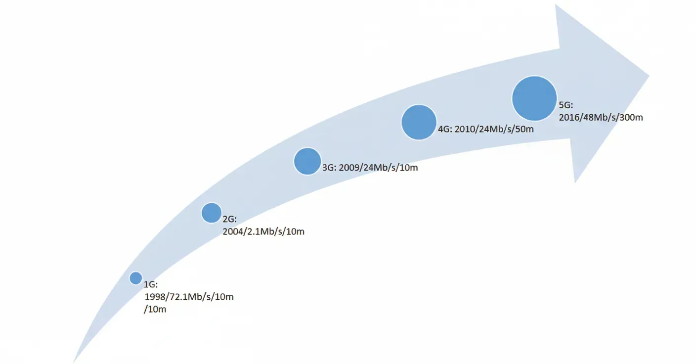
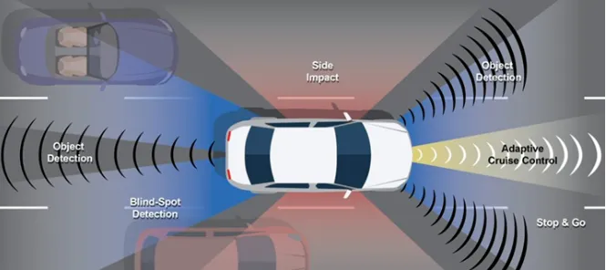
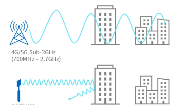
In 5G handsets, millimeter-wave phased arrays provide the beamforming gain needed for reliable links at 24–40 GHz despite high propagation loss. Automotive radar at 24 GHz, 77 GHz, and 79 GHz uses phased arrays for precise angular resolution and simultaneous tracking of multiple targets. Satellite ground terminals, such as those in LEO constellations, employ dense arrays of hundreds or thousands of elements to form narrow, electronically steered beams that track fast-moving satellites without mechanical motion.
Design and Manufacturing Challenges
Millimeter-wave phased arrays impose tight tolerances on phase and amplitude matching across many channels. Thermal management of power amplifiers, low-loss power distribution, and precise synchronization become critical at scale. Fabrication must control trace dimensions, via inductance, and dielectric uniformity to maintain beam coherence. Yield and calibration complexity increase with element count, especially for large-format arrays used in radar or satellite payloads.
Materials and PCB/FPC Relevance
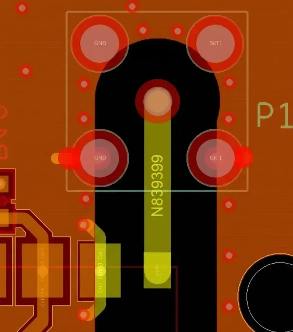
PCB material selection directly affects insertion loss, phase stability, and manufacturing yield. Low-loss dielectrics such as PTFE, hydrocarbon ceramics, or liquid-crystal polymer laminates maintain consistent permittivity and low dissipation factor at millimeter-wave frequencies. Copper surface roughness influences conductor loss; rolled copper foils are often preferred for reduced skin-effect losses. Controlled-impedance microstrip, stripline, and coplanar waveguides require tight tolerances on dielectric thickness and etch accuracy. HDI techniques support dense routing of control lines and power distribution. Flexible printed circuits enable compact, conformable feed networks or interconnects between array modules. Metal-core or embedded-copper substrates provide thermal paths for high-power amplifiers. Environmental qualification—thermal cycling, vibration, and humidity exposure—further influences substrate Tg, coefficient of thermal expansion matching, and surface-finish selection.
Industry Trends and System Integration
Expansion of 5G millimeter-wave networks, automotive radar for autonomous driving, and commercial LEO satellite constellations continues to drive demand for cost-effective, scalable phased arrays. Hybrid analog-digital beamforming, antenna-in-package solutions, and software-defined reconfiguration reduce component count while supporting wider bandwidths. These trends increase the importance of design-for-manufacturability practices that balance electrical performance with production scalability.
PCB and Electronic Manufacturing Relevance
PCB fabrication and assembly processes are essential to realizing millimeter-wave phased-array performance. Precise etching, laser-drilled microvias, sequential lamination, and advanced surface finishes enable the low-loss transmission lines and dense interconnects required for phase coherence. Thermal management solutions maintain amplifier efficiency, while rigorous impedance testing and S-parameter verification confirm array integrity before integration. These manufacturing capabilities allow electronics suppliers to deliver RF modules, beamforming networks, and integrated antenna boards that meet the stringent electrical, thermal, and environmental requirements of 5G infrastructure, automotive radar, and satellite ground terminals.
Conclusion
Millimeter-wave phased arrays combine large available bandwidth with electronic beam steering to address the propagation challenges inherent at high frequencies. Success in production systems depends on precise control of phase and amplitude across the array, supported by low-loss PCB materials, tight fabrication tolerances, and robust thermal management. PCB technologies that deliver controlled-impedance routing, high-density interconnects, and reliable environmental performance directly enable the compact, high-performance electronics required for modern millimeter-wave applications.