In the article "Transmission Lines" we introduced several common transmission-line types. Among PCB-level lines, the microstrip is the most widely used. Previous articles have provided detailed coverage of RF topics and microstrip variants such as microstrip discontinuities, microstrip versus coplanar waveguide with ground, microstrip design methods, and microstrip elements. As a common transmission line, microstrip merits further discussion. This article focuses on a specific design detail: loss.
For any RF transmission line, loss is one of the most important parameters. Even a small loss in a valuable RF signal can significantly affect the entire system. Ideally the target loss is zero—an ideal lossless transmission line. In practice, we must reduce the loss magnitude as much as possible. How can transmission-line loss be reduced?
Overview of Loss Components
Microstrip loss is generally higher than that of air waveguides or coaxial lines, particularly when the microstrip forms part of a component; its impact then increases accordingly. Microstrip loss typically comprises three parts: dielectric loss, conductor loss, and radiation loss.
1. Dielectric Loss
Dielectric loss arises from the substrate material of the microstrip. When an electric field passes through the dielectric, molecular polarization and lattice interactions produce heat dissipation. The loss tangent is the basic parameter used to quantify dielectric loss, denoted tanδ, where δ is the dielectric loss angle. Physically, δ represents the phase difference between the current density vector and the electric field vector in an alternating field. The loss tangent is given by the following relation:
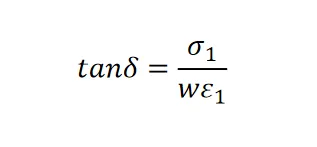
The figure below shows typical curves of dielectric constant ε, loss tangent tanδ, and power versus frequency for dielectric materials.
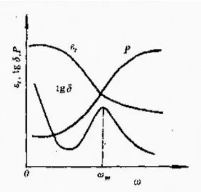
1) At very low applied field frequency (omega -> 0), all polarization mechanisms can follow the applied field, so polarization loss is absent and the dielectric constant reaches its maximum. Since tgδ = σ/(ωε), tgδ -> infinity as omega -> 0. As frequency increases, tgδ decreases.

2) As frequency increases further, relaxation polarizations begin to lag the external field. Their contribution to the dielectric constant decreases, so εr reduces with increasing frequency. In this frequency range, because omega*tau << 1, tgδ increases with frequency and the dissipated power Pw also increases.

3) At high frequency, εr approaches ε∞ and is then dominated by electronic (displacement) polarization, so εr tends to a minimum. When omega*tau >> 1, tgδ decreases with increasing frequency and tgδ -> 0 as omega -> infinity.
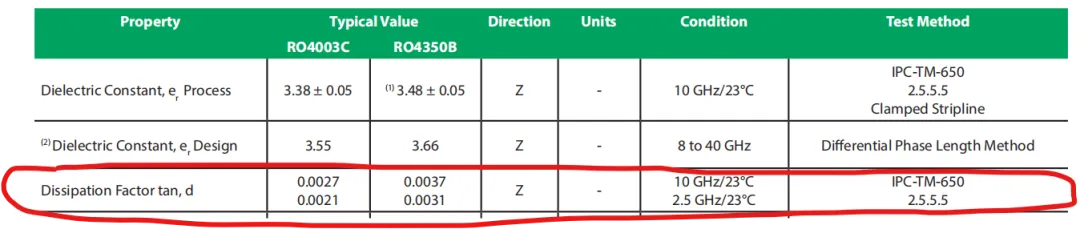
Therefore, when selecting a substrate material, pay attention to the relationship between the operating frequency and the material's loss tangent, and use values close to the operating frequency when performing simulations. For example, Rogers materials RO4003C and RO4350B provide loss-tangent values at 10 GHz and 2.5 GHz respectively.
Air also has dielectric loss, but its value is very small and often negligible in design. Thus, a partially filled dielectric microstrip has lower dielectric loss than a fully filled one, and a microstrip generally has lower dielectric loss than a stripline. Humidity increases dielectric loss.
2. Conductor Loss
Conductor loss is due to the finite conductivity of the microstrip conductor and the ground plane. Current flow causes thermal dissipation. At high frequency, the skin effect reduces the effective conductor cross section, increasing conductor loss. In most cases, conductor loss is the dominant component of microstrip loss.
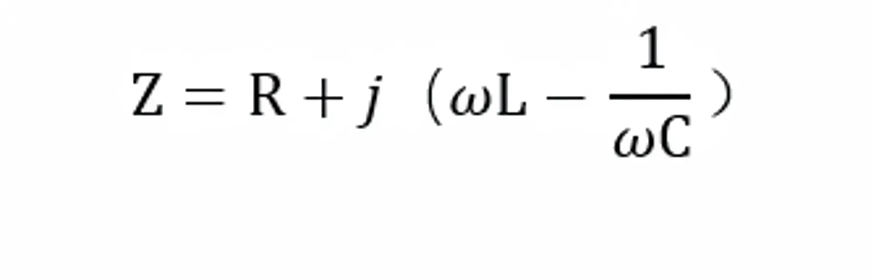
Conductor loss corresponds to resistive loss. Note that impedance Z in RF is not the same as DC resistance. Z includes both resistance and reactance; the resistive component is usually very small and can often be neglected when calculating the characteristic impedance Z0.
However, conductor loss is real. It depends on the metal conductivity: higher conductivity yields lower conductor loss. At DC or low frequency, resistance R0 can be approximated by:
Here, ρ is the resistivity of the metal (the inverse of conductivity) and A is the conductor cross-sectional area.
As frequency increases, the skin effect concentrates current near the conductor surface, decaying exponentially inward. The skin depth is computed as follows:
Thus conductor loss is concentrated within the skin depth δ of the conductor thickness. Which conductor surface (top or bottom) contributes more to loss, and how conductor width affects loss, will be examined in a later article using simulation.
3. Radiation Loss
Microstrip is a semi-open transmission line, so radiation or leakage can cause energy loss. Reducing substrate thickness concentrates the field between the line and the ground plane, which effectively reduces radiation loss. However, nonuniformities or resonances in the microstrip can significantly increase radiation loss. In practice, adding a metal shield can prevent radiation, reduce loss, and limit coupling to other circuits.
Appendices
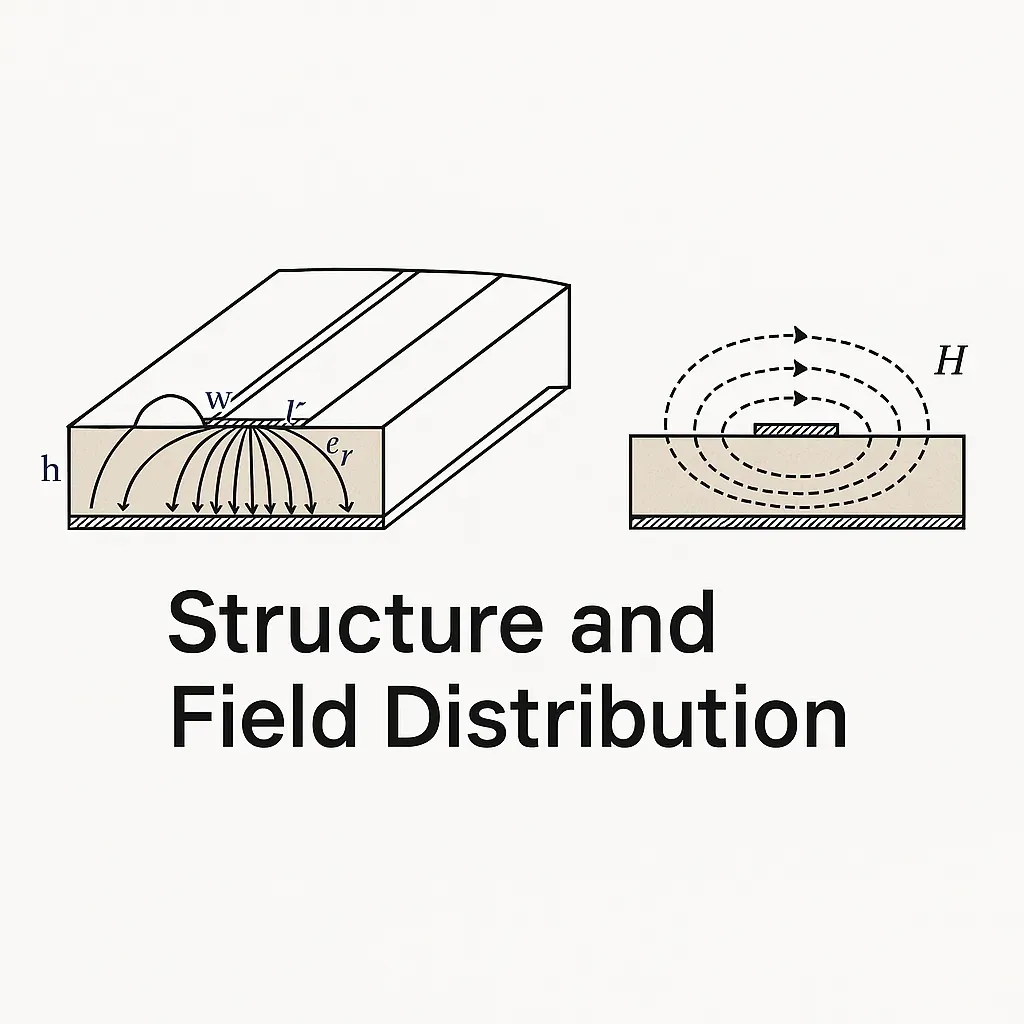
Appendix: Microstrip Field Plot