A signal generator produces electrical signals with selectable frequencies, waveforms, and output levels. It is commonly used as a test source or excitation source for measurements and device characterization.
Overview
A typical signal generator can produce low-frequency sine signals from about 20 Hz to 200 kHz. Besides voltage outputs, some models provide power outputs. They are widely used to test or service low-frequency amplifiers, measure frequency response, gain, and bandwidth, and serve as modulation inputs for radio-frequency signal generators. Signal generators are also used to provide AC reference voltages when calibrating electronic voltmeters.
Low-Frequency Signal Generator Principle
The low-frequency generator architecture typically includes a main oscillator stage, an output-level adjustment potentiometer, a voltage amplifier, an output attenuator, a power amplifier, an impedance matcher (output transformer), and an indicator voltmeter.
Common Types of Signal Generators
Signal generators come in several types. Common categories include:
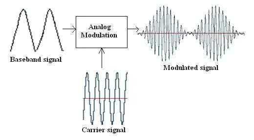
- RF signal generators: Generate radio-frequency signals and typically operate in high-frequency bands. Used in wireless communication, radar, and spectrum analysis. They can produce continuous-wave, frequency-modulated, amplitude-modulated, and pulse signals.
- AF (audio frequency) signal generators: Generate audio-band signals for sound reinforcement, audio testing, and calibration. They can produce sine, square, and swept signals.
- Baseband signal generators: Produce low-frequency or digital signals for data communication, signal modulation, and precision measurements. They can generate various digital patterns and modulation formats such as OFDM and PCM.
Main Applications
- Circuit debugging and testing: Excite the device under test to verify operation, measure performance, and locate faults.
- Communication system testing: Emulate specific channel conditions to evaluate the performance of communication equipment.
- Spectrum analysis: Generate signals with defined frequency and power for measuring and analyzing the radio spectrum.
- Audio equipment calibration: Produce audio signals of specified frequency and amplitude to calibrate audio devices.
Signal Generator vs. Oscilloscope
Signal generators and oscilloscopes are complementary lab instruments with distinct roles:
- Signal generator: Produces electrical signals of various waveforms and frequencies. Parameters such as frequency, amplitude, and phase are adjustable. Typical uses include circuit stimulation, measurement, and driving other equipment.
Usage:- Select the required waveform (sine, square, pulse, etc.).
- Set output frequency, amplitude, and phase as needed.
- Connect the generator output to the circuit or device under test.
- Oscilloscope: Observes and measures electrical signal waveforms. It displays voltage versus time to help engineers and technicians analyze circuit behavior and faults. Oscilloscopes often provide multiple input channels and trigger functions for capturing signals.
Usage:- Connect the voltage signal to the oscilloscope input.
- Adjust timebase and vertical scale to display the waveform fully.
- Set trigger conditions to obtain a stable waveform display.
- Observe the waveform and perform measurements and analysis.
Key differences: the signal generator outputs signals, while the oscilloscope receives and displays signals. They are often used together for circuit testing and analysis.