










This 4-layer FR4 board with 1.6mm finished thickness, 0.15mm minimum hole size, blind vias, and specified countersink features required detailed process capability evaluation before production approval. Key parameters included TG170 material, immersion silver surface finish, and precise depth control for countersunk holes reaching 1.35mm.
Project Requirements: Small-Hole HDI and Depth-Controlled Countersinks
The 162 × 73 mm single-piece 4-layer PCB ( #FR4-20260130-040 ) construction incorporates HDI elements with one stage of blind vias and multiple 0.15mm holes. Customer specifications called for 1oz copper across layers, 1.6mm finished board thickness, and immersion silver finish. A notable feature is the set of countersunk holes fabricated with copper pads, requiring controlled depth to approximately 1.35mm while maintaining structural integrity.
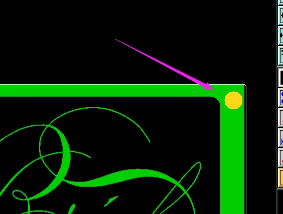
Figure 1: countersunk holes are fabricated as plated holes on the copper layer
During engineering review, the combination of ultra-small drill sizes and depth precision emerged as the primary manufacturing challenge. The provided stackup and panel data were verified, with adjustments made to align with available core materials after confirming no standard 1.5mm core stock was readily available.
Drilling Capability Limits for 0.15mm Holes in HDI Structures
Drilling 0.15mm holes, especially in blind via configurations, pushes the boundaries of standard mechanical drilling processes. At this diameter, drill bit deflection, heat generation, and hole wall quality become critical variables. Our process data indicates that 0.15mm represents the lower end of reliable mechanical drill capability for 1.6mm boards, where aspect ratios approach 10:1 or higher in certain stackup zones.
In my experience reviewing similar builds, smaller diameters increase the risk of drill breakage or wander, particularly when combined with HDI blind vias that require precise registration. We evaluated the provided gerber data and confirmed that optimized spindle speeds, peck cycles, and high-quality carbide tools would be necessary to maintain positional accuracy and hole quality within acceptable limits.
| Hole Parameter | Specification | Process Window | Capability Assessment |
|---|---|---|---|
| Minimum Hole Size | 0.15mm | 0.15-0.20mm typical | At limit; requires enhanced controls |
| Aspect Ratio (est.) | ~10:1 | Up to 12:1 viable | Marginal with HDI elements |
| Positional Tolerance | Strict per drawing | ±0.05mm standard | Achievable with calibration |
Countersink Depth Control and Material Thickness Considerations
The countersunk holes specified at approximately 1.35mm depth on copper features demanded careful Z-axis control. Depth accuracy depends on consistent board thickness, material uniformity, and drill wear compensation. For a 1.6mm finished board, this depth leaves limited remaining material, increasing sensitivity to any lamination variation.
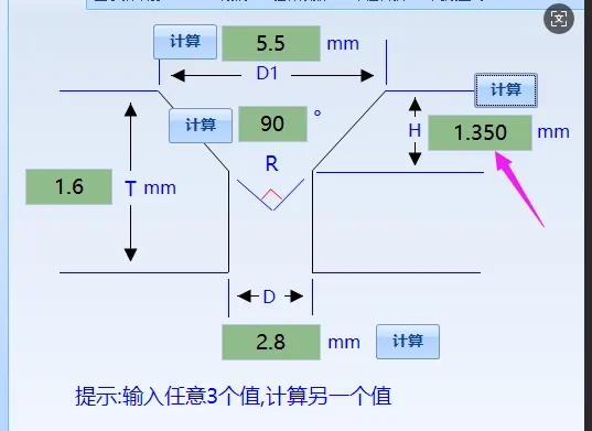
Figure 2: the depth of the countersunk holes is calculated as 1.35mm based on provided parameters
During evaluation, we noted inconsistency risks between the requested 1.6mm thickness and available core materials. After reviewing options (1.53mm vs 1.43mm core without copper), we selected the configuration that best matched the overall stackup while maintaining dielectric spacing suitable for the HDI blind vias. This adjustment was critical to avoid excessive Z-axis expansion or compression during pressing that could shift final depth outcomes.
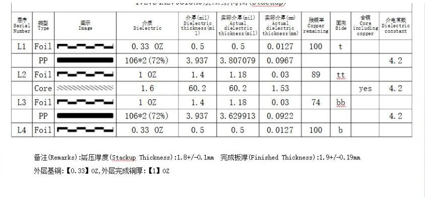
Figure 3: 1.53 mm for inner layers and control the finished product thickness to 1.9 mm
According to IPC-6012 performance criteria, depth-controlled features must maintain repeatability to prevent functional issues such as incomplete countersink or substrate damage. Our assessment confirmed the 1.35mm target was feasible but required first-article cross-sections for validation.
| Parameter | Requested | Typical Control | Manufacturing Note |
|---|---|---|---|
| Finished Thickness | 1.6mm | ±0.10-0.15mm | Core selection impacts final result |
| Countersink Depth | 1.35mm | ±0.08-0.12mm | Tool monitoring essential |
| Surface Finish | Immersion Silver | Standard process | Compatible post-depth drilling |
Lamination Process and Material Performance Evaluation
Using S1000-2M TG170 FR4, the lamination process for 1.6mm total thickness involves balancing resin flow with copper distribution. The 1oz copper configuration provides relatively even thermal mass compared to heavier weights, supporting better thickness uniformity. However, the absence of readily available matching core thickness required procurement adjustments that were factored into the 13-day delivery timeline.
I observed in the capability review that minor variations in core thickness directly influence final pressed thickness and, consequently, the effective depth of countersunk features. The selected material option provided sufficient margin while preserving impedance and signal integrity characteristics expected in HDI designs.
Plating and Surface Finish Integration Challenges
Immersion silver was confirmed after disregarding initial ENIG references in the fab drawing. This finish requires clean hole walls post-drilling, particularly important for the 0.15mm holes and countersinks. Our plating line parameters were adjusted to ensure adequate silver deposition without bridging in fine features or compromising the blind via barrels.
Solder mask color consistency was addressed as a minor clarification point, resolved through final file confirmation to avoid print variations that could affect inspection.
Validation Through Testing and Cross-Section Analysis
Production approval followed detailed first-article verification. Cross-sections of sample boards confirmed countersink depth accuracy, hole wall quality for 0.15mm drills, and blind via plating integrity. 100% flying probe testing was implemented to validate electrical continuity across all layers and features. Thickness measurements at multiple points verified compliance with the 1.6mm target within acceptable tolerance.
Mechanical and thermal stress simulations aligned with IPC-TM-650 methods supported confidence in long-term reliability for the HDI elements under expected operating conditions.
| Validation Method | Focus Area | Acceptance Criteria | Outcome |
|---|---|---|---|
| Microsection Analysis | Depth & Via Quality | Per IPC-A-600 | Compliant |
| Flying Probe | Electrical Integrity | 100% net coverage | Passed |
| Thickness Mapping | Panel Uniformity | 1.6mm ± tolerance | Within limits |
Conclusion: Production Release After Capability Confirmation
The engineering assessment confirmed that the 0.15mm hole size with HDI blind vias and 1.35mm countersink depth can be produced reliably through targeted process controls and material adjustments. All critical parameters, including thickness and surface finish, aligned with stable manufacturing windows following stackup and file verifications. This board advanced to production with confidence in meeting the specified requirements.
FAQs
Q1: What makes 0.15mm holes challenging in 4-layer HDI boards?
A1: At this diameter, drill stability, aspect ratio, and plating reliability become limiting factors. Tight process controls on speed, peck depth, and tool condition are required to maintain yield and hole quality.
Q2: How is countersink depth accuracy maintained across production panels?
A2: Depth control relies on consistent board thickness, regular drill calibration, and compensation for material compression. Cross-section verification on first articles helps establish reliable offsets.
Q3: Why does core material availability affect thickness capability?
A4: Non-standard core thicknesses may require custom procurement, impacting lamination symmetry and final pressed thickness. Selecting the closest available option while validating dielectric spacing is standard practice.
Q5: When is immersion silver preferred over other finishes for fine-feature boards?
A5: Immersion silver offers good solderability and conductivity for small holes and high-frequency applications, provided post-drill cleanliness is achieved. It integrates well when ENIG is not required.
Q6: What role does 100% electrical testing play in HDI verification?
A6: It ensures all blind vias and fine holes meet continuity and isolation requirements, catching any plating or drilling defects before shipment.






