Introduction
Drone avionics systems form the core of unmanned aerial vehicles, integrating flight controllers, sensors, communication modules, and power distribution circuits on printed circuit boards. These PCBs must operate reliably in dynamic flight conditions while meeting stringent size, weight, and power constraints. Drone avionics PCB design presents unique engineering hurdles due to the need for high performance in compact forms. Engineers face pressures to optimize every aspect, from signal integrity to mechanical durability, to ensure mission success. This article explores the primary challenges in drone avionics PCB design and provides structured solutions grounded in established engineering practices. By addressing these issues systematically, designers can enhance drone reliability and efficiency.
What Is Drone Avionics PCB Design and Why It Matters
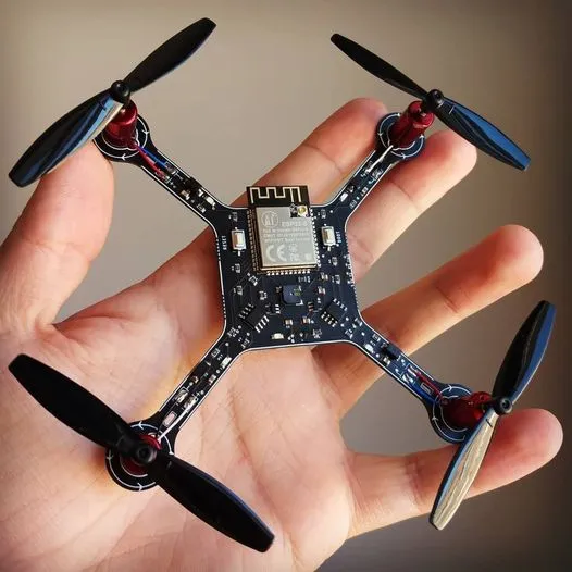
Drone avionics PCB design involves creating circuit boards that house critical electronics for navigation, stabilization, telemetry, and propulsion control. These boards connect microcontrollers, inertial measurement units, GPS receivers, and radio transceivers in a tightly integrated package. Unlike consumer electronics PCBs, drone versions prioritize survival in airborne environments with rapid maneuvers and external disturbances. The design process requires balancing electrical performance, thermal dissipation, and structural integrity from schematic capture through fabrication. It matters because suboptimal designs lead to reduced flight times, signal failures, or crashes, compromising safety and operational effectiveness. For electric engineers, mastering drone avionics PCB design directly impacts the viability of applications in surveillance, delivery, and inspection.
Effective avionics PCBs enable autonomous operations by ensuring precise data processing and low-latency control loops. They must support high-speed interfaces like SPI, I2C, and UART while minimizing electromagnetic interference. Industry demands for smaller, longer-endurance drones amplify the complexity, pushing designers toward advanced fabrication techniques. Reliability under vibration and temperature swings becomes paramount for commercial and professional use. Ultimately, robust drone avionics PCB design translates to extended battery life and repeatable performance across missions.
Key Challenges in Drone Avionics PCB Design
Miniaturized Drone PCB Challenges
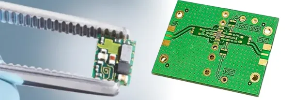
Miniaturized drone PCB design demands extreme component density to fit avionics into airframes with limited volume. High-density interconnects and fine-pitch components challenge routing and assembly precision, often requiring via-in-pad configurations. Signal integrity degrades with closely packed traces, leading to crosstalk and reflections at operating frequencies above 100 MHz. Thermal hotspots emerge from concentrated power dissipation in small areas, complicating heat spreading. Fabrication tolerances tighten to microns, increasing yield risks during multilayer lamination. These factors collectively strain standard design flows, necessitating specialized strategies.
Lightweight Drone PCB Challenges
Achieving lightweight drone PCB construction involves selecting thin cores and minimal copper weights without sacrificing strength. Reduced board thickness heightens warpage risks during reflow soldering, potentially misaligning components. Material choices must balance low density with mechanical stability, as thinner laminates flex under aerodynamic loads. Power planes thin out, raising resistance and voltage drops in distribution networks. Assembly processes demand careful handling to avoid delamination from handling stresses. Overall, lightweight drone PCB design trades durability for mass reduction, requiring meticulous stack-up planning.
Power Management Drone PCB Challenges
Power management drone PCB design grapples with efficient distribution from compact batteries to diverse loads like motors and sensors. Voltage regulators generate heat in confined spaces, demanding isolated planes and vias for dissipation. Current surges during propulsion demand wide traces and stitching to prevent hotspots. Battery monitoring circuits must integrate seamlessly without adding parasitic inductance. EMI from switching converters couples into sensitive analog paths, disrupting sensor accuracy. These issues limit flight endurance and stability, underscoring the need for optimized layouts.
Vibration Resistant Drone PCB Challenges
Vibration resistant drone PCB design counters high-frequency oscillations from propellers and gusts, which fatigue solder joints and traces. Mechanical resonances amplify stresses at mounting points, risking microcracks in vias. Flexible connections between rigid sections fail under cyclic loading without damping. Component leads loosen over time, altering electrical characteristics. Environmental factors like humidity exacerbate corrosion in exposed areas. Adhering to IPC Class 3 requirements helps mitigate these reliability concerns through enhanced inspection criteria.
Additional challenges include electromagnetic compatibility and thermal management. High-speed signals from IMUs demand controlled impedance to preserve timing accuracy. Operating temperatures swing widely, stressing material Tg limits.
Practical Solutions and Best Practices
Solutions for Miniaturized Drone PCB Design
Engineers address miniaturized drone PCB challenges through high-density interconnect technology, employing microvias and blind vias for vertical transitions. Layer counts of four to eight separate power, ground, and signals, reducing crosstalk via dedicated planes. Component embedding within substrates further shrinks footprints while improving thermal paths. Simulation tools verify signal integrity pre-layout, adjusting trace widths and lengths for matched impedances. Fabrication partners must support fine-line etching below 50 microns. These practices yield compact boards with maintained performance.
Solutions for Lightweight Drone PCB Design
Lightweight drone PCB solutions leverage high-Tg FR-4 or polyimide laminates with thicknesses under 0.8 mm. Hybrid rigid-flex constructions fold to conform to airframe contours, eliminating heavy connectors. Copper pour optimization minimizes mass while ensuring rigidity at standoffs. Selective plating on high-current paths preserves conductivity without excess weight. Post-fabrication, conformal coatings add protection without bulk. Stack-up symmetry prevents warpage, aligning with IPC-6012 qualification specs for rigid boards.
Solutions for Power Management Drone PCB Design
For power management drone PCB design, dedicate inner layers to planes with extensive via stitching for low-impedance returns. Buck converters position near loads, with input capacitors decoupling noise. Thermal vias under ICs channel heat to chassis grounds. Current sensing shunts integrate directly into traces for accuracy. Ground partitioning isolates digital and analog sections, curbing EMI. These techniques extend battery life by minimizing losses.
Solutions for Vibration Resistant Drone PCB Design
Vibration resistant drone PCB solutions incorporate mounting holes with oversized pads and epoxy potting for shock absorption. Solder fillet profiles follow IPC-A-610 guidelines for joint strength. Damping adhesives between layers attenuate resonances. Rigid-flex transitions use strain relief bends. Component selection favors low-profile packages with locking features. Accelerated life testing validates endurance under profiled spectra.
Troubleshooting Insights for Drone Avionics PCBs
Common issues in drone avionics PCB design include intermittent sensor dropouts from poor grounding. Verify star-point schemes isolate returns, measuring impedance under load. Overheating regulators signal inadequate vias; redistribute with copper fills. Vibration-induced opens trace to unsupported traces; reinforce with polygons. Post-assembly, X-ray inspection reveals voids early. Iterative prototyping refines these fixes logically.
Conclusion
Drone avionics PCB design navigates miniaturization, weight, power, and vibration challenges through targeted engineering. Lightweight drone PCB, power management drone PCB, and vibration resistant drone PCB strategies enhance overall system performance. Best practices like multilayer stack-ups and standards compliance ensure reliability. Engineers benefit from structured approaches balancing trade-offs. Future advancements in materials promise even tighter integrations. Prioritizing these elements drives successful drone deployments.
FAQs
Q1: What materials suit lightweight drone PCB design?
A1: Lightweight drone PCB design favors high-Tg laminates and polyimides for low mass and stability. Thin cores reduce weight while maintaining rigidity. Hybrid rigid-flex options fold efficiently. These choices support extended flights without excess bulk. Always verify CTE matching for reliability.
Q2: How does vibration affect drone avionics PCB design?
A2: Vibration in drone avionics PCB design fatigues joints and shifts components. High frequencies from props demand damping layers. Mounting strategies distribute loads evenly. Conformal coatings seal against ingress. Testing simulates profiles for validation.
Q3: What are key power management drone PCB techniques?
A3: Power management drone PCB techniques include dedicated planes and thermal vias. Decoupling caps stabilize supplies. Trace widening handles surges. Partitioning prevents noise coupling. Efficiency gains prolong missions.
Q4: Why prioritize miniaturized drone PCB in avionics?
A4: Miniaturized drone PCB enables compact airframes for agility. HDI reduces size while preserving signals. Embedding shrinks profiles. Yield improves with tight tolerances. It optimizes SWaP constraints effectively.
References
IPC-6012E — Qualification and Performance Specification for Rigid Printed Boards. IPC, 2017
IPC-A-610H — Acceptability of Electronic Assemblies. IPC, 2019
J-STD-001G — Requirements for Soldered Electrical and Electronic Assemblies. IPC, 2011


