Why Design a Personal Health Tracker on a DIY Printed Circuit Board?
The rise of wearable technology has revolutionized personal health monitoring, moving from clinical settings to everyday life with devices like smartwatches and fitness bands. For electronics enthusiasts, crafting a simple health monitor offers an excellent entry point into embedded systems, sensor integration, and compact PCB design. This kind of hands-on project not only demystifies the technology but also delivers tangible insights into physiological data, such as heart rate or temperature.
Embarking on a custom PCB project for a wearable device provides unparalleled control over its features, aesthetics, and functionality. It’s a deeply gratifying experience, blending technical problem-solving with creative expression. Moreover, the skills acquired during such a build are directly applicable to a wide array of other electronic endeavors, making it a valuable learning experience for any hobbyist.

What Key Components Make Up a Simple Wearable Health Monitor?
Before beginning the design phase, it's beneficial to understand the fundamental building blocks of a basic health monitoring device. At its core, this type of monitor captures biological signals using specialized sensors. These signals are then transmitted to a central processing unit, usually a microcontroller, which interprets the data and presents it to the user, typically via a small display or a wireless connection to another device.
Core Electronic Components
For a wearable application, the HDI PCB must be engineered for minimal size, weight, and power consumption to ensure user comfort and extended battery life.
● Sensors: To measure heart rate, a photoplethysmography (PPG) sensor is commonly used. This sensor works by emitting light (often in the 540-570 nm wavelength range for optimal signal) and detecting changes in blood volume in the capillaries, which correspond to heartbeats.
● Microcontroller: A compact, energy-efficient microcontroller, frequently an Arduino-compatible module, handles the sensor data acquisition and processing.
● Power Supply: A small rechargeable lithium-ion battery (e.g., 3.7V, 100-200mAh) provides portable power, often managed by a voltage regulator to ensure stable output (e.g., 3.3V or 5V).
● Output Interface: Data can be displayed on a miniature OLED screen or transmitted wirelessly through a Bluetooth module to a smartphone for logging and analysis.
How Do You Plan and Lay Out Your Wearable PCB Design?
The initial phase of any fast turn custom PCB project is meticulous planning, especially when dealing with the size constraints inherent in wearable electronics. Start by clearly defining the core function of your health monitor. For instance, focusing solely on heart rate monitoring simplifies the component selection and design, making it more manageable for beginners.
Initial Design Considerations
Begin with a preliminary sketch of your component arrangement. For devices worn on the wrist, aim for compact PCB dimensions, ideally not exceeding 30mm by 30mm. Prioritize low power consumption by choosing components known for their efficiency, such as microcontrollers that feature sleep modes to significantly reduce current draw—often to less than 1mA—during idle periods. This thoughtful planning helps maximize battery life in a small form factor.
Suggested Reading: Designing Wearable PCBs with KiCad: A Step-by-Step Guide
What Are the Steps for Assembling Your Custom Health Monitor PCB?
Once your PCB design is finalized and the board has been fabricated, the next exciting stage is assembly. This involves carefully attaching all the selected components to the bare circuit board.
Component Soldering and Connection Verification
● Soldering Sequence: Begin by soldering the smallest components first, such as resistors and capacitors, then progress to larger items like the microcontroller and sensors. Use a fine-tipped soldering iron, typically set around 300°C, to ensure precise and safe connections.
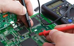
● Connection Testing: After soldering, use a multimeter to check for any unintentional short circuits or open connections. Verify that the sensor is outputting an expected signal—for example, a PPG sensor might show voltage fluctuations between 0.5V and 1.5V when in contact with skin.
● Microcontroller Programming: Load your microcontroller with code designed to read raw sensor data, process it (e.g., applying a bandpass filter between 0.5-5Hz to isolate heart rate signals), and translate it into a readable heart rate value.
How Do You Test and Refine Your DIY Wearable Health Device?
Rigorous testing is crucial to confirm that your basic health monitor operates accurately and reliably. Place the sensor firmly against your skin—such as your wrist or fingertip—and observe the readings. Compare the device’s heart rate output against a commercial monitor or your known resting heart rate, which typically falls between 60 and 100 beats per minute (BPM).
Calibration and Enclosure Design
● Sensor Calibration: Fine-tune the sensor’s detection thresholds within your code. If, for instance, a PPG sensor’s heartbeat signal peaks at 1.2V, set a detection threshold slightly below this (e.g., 1.0V) to minimize false positives. Collect data over several minutes to assess consistency, making adjustments if readings show excessive variability.
● Building a Wearable Case: For wearable devices, the housing must be both comfortable and robust. Consider 3D printing a custom enclosure or modifying a small plastic case. Ensure there's an opening that allows direct skin contact for the sensor. Secure the device with a soft, skin-friendly strap made from materials like silicone or fabric, designed for prolonged wear. Aim for a total device weight, including the PCB and battery, under 20 grams to maximize comfort and prevent irritation during extended use
What Are Common Challenges in Wearable Electronics Projects?
Developing a simple health monitor isn't without its hurdles. One frequent issue is sensor accuracy, which can be compromised by user movement or insufficient skin contact, leading to inconsistent readings. Mitigate this by ensuring the sensor is snugly secured against the skin and by implementing software-based filters to eliminate signal noise. Battery longevity also presents a significant challenge, as wearable devices are expected to function for at least a full day on a single charge; optimizing power consumption at both the hardware and software levels is therefore paramount.
Furthermore, the compact size requirements for wearable PCBs can make soldering intricate. Overly close component placement risks short circuits. If you are new to soldering miniature components, it's advisable to allow for slightly more space in your PCB layout.
How Can You Enhance Your Basic Health Monitor’s Capabilities?
Once your foundational health monitor is fully operational, you might consider expanding its features to increase its utility. Integrating a temperature sensor, for example, allows for tracking body heat, with typical healthy adult readings ranging from 36.1°C to 37.2°C. Alternatively, incorporating a Bluetooth module enables wireless data transmission to a smartphone, facilitating long-term health trend analysis.
Each additional feature will deepen your understanding of wearable electronics and advanced PCB design principles. However, remember that new functionalities often lead to increased power draw and larger PCB footprints. It's crucial to strike a practical balance between enhanced features and the core requirements of a comfortable, portable wearable device.


