What is an Engine Control Unit (ECU) and How Does an ECU PCB Function?
An Engine Control Unit (ECU) serves as the central intelligence of an engine system, orchestrating crucial operations such as fuel delivery, ignition timing, and air intake. A DIY ECU PCB project involves constructing a personalized circuit board to fulfill these roles, often leveraging accessible microcontrollers like Arduino alongside open-source engine management software. Undertaking the creation of your own ECU PCB offers distinct advantages: it provides considerable cost savings, enables complete customization to specific needs, and fosters a profound understanding of how engine management systems function.
A typical ECU system is responsible for managing several key engine parameters:
- Fuel Injection: Regulates the precise volume of fuel delivered to the engine cylinders, adjusting based on live sensor inputs.
- Ignition Timing: Determines the exact moment each spark plug fires, often achieving accuracy within 1-2 degrees of crankshaft rotation.
- Idle Speed Control: Ensures the engine maintains a consistent and stable idle speed, generally between 600-800 RPM for most passenger vehicles.
- Emissions Management: Modifies engine parameters to minimize the output of harmful exhaust emissions.
For a custom engine management system, your DIY ECU PCB must effectively interface with these diverse sensors and actuators, process data rapidly—often at rates of 100-200 Hz for real-time responsiveness—and reliably execute commands.
Why Create Your Own DIY ECU for Custom Engine Control?
Undertaking a DIY ECU PCB project involves constructing a personalized circuit board tailored specifically to your engine's requirements, often leveraging accessible microcontrollers like Arduino alongside open-source management software. But why go through the effort of building one from scratch?
-
Substantial Cost Savings: Commercial aftermarket ECUs can easily cost upwards of $1,000 to $3,000. By sourcing your own components and fabricating your own board, you can build a highly capable unit for a fraction of that price.
-
Unrestricted Customization: Off-the-shelf units often lock you into proprietary software or specific hardware configurations. Building your own allows you to dictate everything from the number of injector drivers to the specific communication protocols used.
-
Profound Educational Value: For tech enthusiasts and engineers, this endeavor perfectly merges the worlds of digital electronics and automotive mechanics. It provides a hands-on learning experience that forces you to deeply understand engine dynamics, circuit design, and embedded programming.
What Components and Tools Are Needed for a DIY ECU Arduino Project?
Initiating your own ECU PCB construction requires a careful selection of appropriate tools and electronic components. Given the hobbyist nature of this project, the focus will be on utilizing an Arduino as the central microcontroller due to its affordability, user-friendliness, and extensive community support for open-source engine control applications.
Essential Electronic Components
- Microcontroller: An Arduino board, such as the Arduino Mega or Uno, is ideal. It should possess sufficient processing power (e.g., a 16 MHz clock speed for the Uno) and an adequate number of input/output pins (at least 20 for more complex configurations).
- Sensors: Critical sensors include a crankshaft position sensor, throttle position sensor, a MAP (Manifold Absolute Pressure) sensor for pressure readings (typically providing a 0-5V output), and various temperature sensors.
- Actuators: These include fuel injectors and ignition coils, which will require compatible driver circuits, such as MOSFETs, capable of handling currents up to 10A for injectors.
- Power Supply: A stable regulated power supply, either 5V or 12V, with a current capacity of at least 2A, is necessary to power both the Arduino board and connected components.
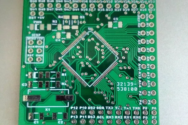
- PCB Materials: You'll need copper-clad board for DIY etching or a professionally fabricated PCB based on your design, along with soldering tools and suitable connectors for creating wiring harnesses.
- Communication Modules: For integration with modern vehicle systems, a CAN bus module (e.g., MCP2515) capable of communication speeds up to 1 Mbps may be required.
Necessary Software Tools
- Open-Source Engine Control Software: Platforms like Speeduino are popular choices, providing readily available firmware specifically designed for Arduino-based ECUs, including code for fuel and ignition mapping.
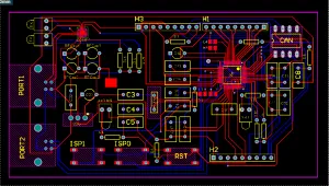
- PCB Design Software: Free design tools such as KiCad are excellent for creating custom ECU PCB layouts, ensuring correct trace widths (e.g., 0.5mm for signal lines, 2mm for power lines).
- Programming Environment: The Arduino IDE is used for writing code, compiling, and uploading the firmware to your Arduino board.
Step-by-Step Guide to Designing and Building an ECU PCB Board
With your tools and components assembled, let's proceed with the design and construction of your custom DIY ECU PCB. This guide assumes a basic understanding of electronics, including soldering techniques and interpreting circuit schematics.
Defining Project Scope
Begin by clearly outlining the specific functions your ECU will manage. For a foundational hobbyist engine management system, concentrate on fuel injection and ignition timing for a single-cylinder or small engine. Compile a list of all sensors and actuators you intend to use, ensuring your chosen Arduino board has a sufficient number of available pins (e.g., 14 digital I/O pins for a basic setup).
Schematic Design
Utilize your chosen PCB design software to develop a detailed schematic that illustrates the connections between your Arduino and all peripheral components. This should include:
- Analog inputs configured for sensor signals (e.g., 0-5V from a throttle position sensor).
- Digital outputs designed to control injectors and ignition, typically through transistors or MOSFETs.
- Power regulation circuitry to step down the vehicle’s 12V supply to the 5V required by the Arduino (e.g., using an LM7805 regulator rated for 1A).
Ensure meticulous attention to proper grounding techniques to mitigate noise interference, which can otherwise cause sensor reading inaccuracies of up to 0.1V.
PCB Layout Creation
Translate your completed schematic into a physical PCB layout. Critical considerations include keeping high-current traces, such as those for injectors, short and wide (at least 2mm) to safely handle currents ranging from 5-10A. Position sensitive analog components geographically distant from noisy digital signal paths to preserve signal integrity. Aim for a compact board size, perhaps around 100mm x 80mm, to allow for convenient enclosure integration.
Suggested Reading: Optimizing ECU PCB Performance: A Guide to Layer Stackup Design
PCB Fabrication
Once your design is finalized, you have two primary options for fabricating the PCB: either etch it yourself at home using a copper-clad board and ferric chloride, or opt for professional manufacturing services. For hand-soldering, ensure the board is designed to accommodate through-hole components, which are generally more manageable for hobbyists than surface-mount devices.
Component Assembly and Soldering
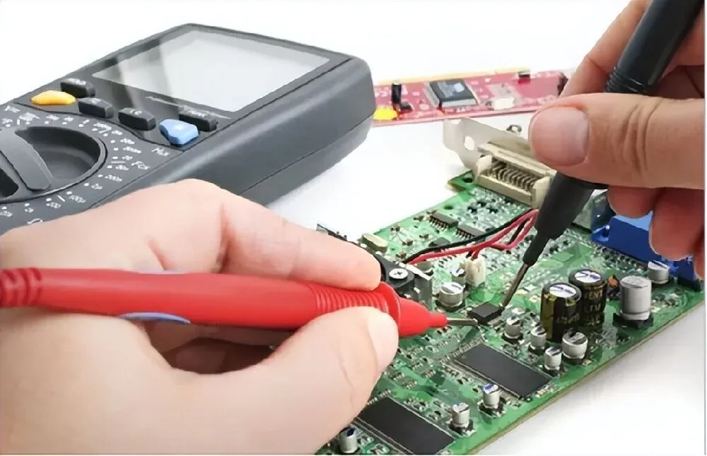
Carefully solder all components onto the PCB. It’s typically best to start with lower-profile components like resistors, then proceed to larger items such as connectors. Always verify the correct polarity for components like capacitors and diodes to prevent damage. Use a multimeter to perform continuity tests, confirming there are no unintended short circuits, particularly on power traces carrying 12V.
Programming the Arduino
Download an appropriate open-source engine control firmware, such as Speeduino, which is compatible with Arduino boards for hobbyist engine management applications. Upload this firmware using the Arduino IDE. Subsequently, configure key settings like injector pulse width (e.g., 2ms at idle) and ignition advance (e.g., 10 degrees before top dead center at 1000 RPM). A tuning interface will be necessary to fine-tune these parameters based on live engine data.
Testing and Troubleshooting
Connect your newly built DIY ECU PCB to either a test engine or a simulated setup. Systematically verify all sensor readings—for example, a MAP sensor should indicate approximately 100 kPa at sea level with the engine off. Confirm that actuators respond as expected, such as hearing an injector click when triggered. Should any issues arise, a logic analyzer can be invaluable for checking signal timing, ensuring that pulses align within 1ms of their expected values.
Common Challenges and Safety Measures in DIY ECU PCB Development
Operating customized electronics in an automotive environment is inherently demanding. Overcoming these hurdles requires strict adherence to safety and design best practices.
-
Managing Electromagnetic Noise: Engine bays generate immense electromagnetic interference (EMI) from high-voltage spark plug wires and alternators. Combat this by using shielded cables for all VR sensor inputs, keeping signal wires away from high-current wires, and utilizing bypass capacitors (e.g., 0.1μF ceramic caps) across sensor inputs on your PCB.
-
Mitigating Heat and Vibration: Under-hood temperatures frequently exceed 100°C alongside violent vibrations. Always house your PCB in a robust, sealed, and potentially potted enclosure. Select automotive-grade components rated for at least 125°C.
-
Electrical Safety Protocols: A vehicle's 12V battery can deliver hundreds of amps in a short circuit condition, easily melting wires and causing fires. Always disconnect the battery before altering wiring harnesses. Additionally, install appropriately rated inline fuses (e.g., 3A or 5A) for your ECU’s main power supply and separate fuse blocks for high-current injector/coil circuits.
-
Processing Limitations: Standard 8-bit, 16 MHz microcontrollers may struggle with the math required for high-RPM, 8-cylinder sequential injection. If you face timing bottlenecks, you may need to utilize batch-fire injection or upgrade to a 32-bit architecture.
Suggested Reading: Designing for Reliability: Best Practices for ECU PCBs in Harsh Environments
The Advantages of Open-Source DIY ECU Systems
Before exploring advanced add-ons, it is worth highlighting why open-source systems represent a paradigm shift in automotive tuning. Open-source communities offer free access to actively developed firmware, bypassing the steep paywalls of proprietary systems. This collaborative environment ensures bugs are patched quickly and new hardware features are integrated rapidly.
Here is a brief comparison highlighting the strengths of the open-source DIY approach:
| Feature | Open-Source DIY ECU | Commercial Aftermarket ECU | Stock OEM ECU |
| Initial Cost | Very Low ($100 - $250) | High ($1,000 - $3,000+) | N/A (Included with vehicle) |
| Customizability | Absolute (Hardware & Software) | High (Software only) | Very Low (Locked by manufacturer) |
| Learning Curve | Steep (Requires electronics & tuning knowledge) | Moderate (Requires tuning knowledge) | Low (Plug-and-play) |
| Community Support | Vast, global enthusiast networks | Direct manufacturer support | Limited (Usually requires dealership or specialized tuners) |
| Feature Upgrades | Free, continuous community updates | Paid software unlocks/upgrades | Extremely rare |
Enhancing Your DIY ECU Arduino System with Advanced Features
Once your foundational DIY ECU PCB is operational, there are numerous avenues to expand its functionality with additional advanced features.
Integrating Data Logging
Consider adding an SD card module to enable data logging. This allows your ECU to record critical engine data, such as RPM and fuel consumption, at a frequency of about 10 Hz for subsequent analysis and performance review.
Bluetooth Monitoring
Incorporate a Bluetooth module, like the HC-05, to facilitate real-time engine monitoring directly on a smartphone. This can operate effectively at standard baud rates, such as 9600, providing convenient access to live operational data.
Advanced Tuning Features
Utilize open-source tuning software to develop sophisticated custom fuel maps. This enables precise adjustments to injector timing, often in increments as fine as 0.1ms, allowing for meticulous optimization of engine performance.
Future Trends in DIY ECU and Custom PCB Design for Multi-fuel Vehicles
As the automotive landscape shifts towards complex alternative fuels and smarter systems, the DIY community is rapidly evolving to keep pace. The simple 8-bit Arduino setup, while excellent for learning, is slowly making way for next-generation hardware and design philosophies.
-
Transition to 32-Bit Microcontrollers: The modern DIY ecosystem is heavily adopting 32-bit ARM Cortex processors (like the STM32 and Teensy boards) and dual-core ESP32 microcontrollers. Operating at speeds up to 600 MHz, these chips easily handle complex math, sequential injection for V8 engines, and native Wi-Fi/Bluetooth capabilities without breaking a sweat.
-
Custom PCB Design for Multi-Fuel Vehicles: With the rise of flex-fuel tuning, hobbyists are creating advanced custom PCB design for multi-fuel vehicles. These modern boards integrate dedicated inputs for ethanol content sensors, allowing the ECU to dynamically interpolate between two completely different fuel and ignition maps in real-time, depending on the exact ratio of gasoline to E85 in the tank.
-
High-Density Interconnect (HDI) PCBs: To fit more processing power and high-current drivers into smaller, waterproof motorsport enclosures, DIYers are utilizing professional fabrication houses to print 4-layer and 6-layer HDI boards. These multi-layer designs allow for dedicated internal ground and power planes, drastically reducing EMI noise and improving thermal dissipation for MOSFETs.
-
AI and Auto-Tuning Integration: While rudimentary auto-tune features already exist in software like TunerStudio (where the software adjusts the VE table based on live O2 sensor feedback), future DIY engine management systems are poised to utilize machine learning algorithms. These will predictively adjust spark timing and fueling based on historical driving data and ambient environmental shifts, creating a self-optimizing engine system.

Begin Your DIY ECU PCB Project Today
Constructing your own ECU PCB provides an exceptional entry point into the world of hobbyist engine management. By combining an Arduino microcontroller, open-source engine control software, and a custom-designed HDI PCB, you can create a highly personalized solution perfectly tailored for your engine project. Each stage of the process—from circuit design to programming and rigorous testing—imparts invaluable knowledge in both electronics and automotive systems.
With this guide as your foundation, you are now well-prepared to commence your DIY ECU PCB project. Proceed methodically, conduct thorough testing at each step, and savor the experience of transforming your engine control concepts into a functional reality. Whether your application is a go-kart, a motorcycle, or a vintage automobile, your custom-built ECU will grant you comprehensive control over its performance and fuel efficiency.
FAQs
Q1: Can an Arduino-based ECU control any type of engine?
A1: While an 8-bit Arduino (like the Mega 2560) is fantastic for port-injected engines with 1 to 4 cylinders running batch-fire or semi-sequential injection, it has limitations. It typically lacks the processing speed required for 8-cylinder fully sequential injection or the complex high-voltage drivers needed for Gasoline Direct Injection (GDI) engines. For highly complex setups or a custom PCB design for multi-fuel vehicles running advanced flex-fuel sensors, you will generally need to upgrade to a faster 32-bit microcontroller (like an STM32 or Teensy) to handle the increased computational load.
Q2: Is a DIY Engine Control Unit reliable enough for racing or heavy use?
A2: The reliability of a custom ECU depends entirely on your build quality. If a board fails, it is rarely the microcontroller's fault; it is usually due to poor soldering, inadequate vibration protection, or a lack of electrical noise filtering. By using high-temperature automotive-grade components, conformal coating the finished board to protect against moisture, and housing it in a durable aluminum enclosure, your DIY unit can easily handle the rigors of track days or autocross. For high-stress environments, utilizing professional manufacturing for your DIY ECU PCB rather than hand-etching is strongly recommended to ensure trace integrity.
Q3: Can a DIY ECU handle turbocharged or supercharged engines?
A3: Yes, absolutely. Managing a forced-induction engine primarily depends on the MAP (Manifold Absolute Pressure) sensor you integrate into your build. While a naturally aspirated engine typically uses a 1-bar MAP sensor, a turbocharged setup requires a 2-bar, 3-bar, or even 4-bar sensor to read positive manifold pressure (boost). You simply wire the higher-capacity sensor to your DIY ECU PCB analog inputs and calibrate it in your software. Furthermore, open-source firmware like Speeduino fully supports closed-loop boost control, allowing you to use a dedicated PWM (Pulse Width Modulation) output to command an electronic boost control solenoid.


