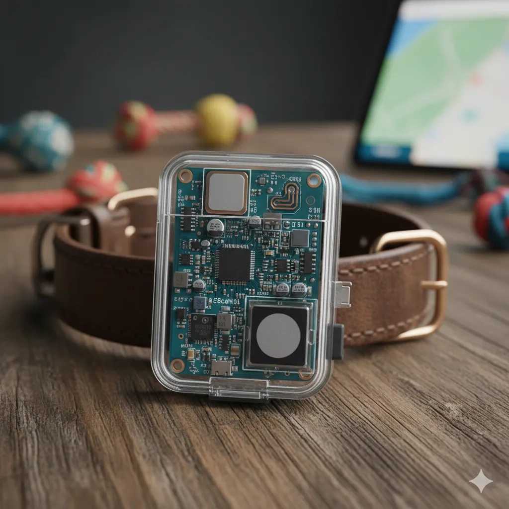
What is a Pet Tracking Module PCB?
A Pet Tracking Module PCB is the central nervous system of any wearable animal tracking device. It is a highly miniaturized, densely packed Printed Circuit Board (PCB) that integrates location services (like GPS), wireless communication (such as Cellular or Bluetooth), microcontrollers, and power management into an ultra-compact footprint. Because these devices are worn by pets—ranging from large dogs to small cats—the PCB must be exceptionally small, lightweight, and rugged enough to withstand constant movement, impacts, and outdoor elements.
In essence, this module transforms raw satellite signals and battery power into actionable location data that pet owners can view directly on their smartphones.
Why Custom PCB Design for Tracking Matters in Pet Trackers?
Pet tracking devices have become indispensable for owners monitoring their animals. These compact gadgets depend entirely on a well-engineered Printed Circuit Board (PCB) to integrate essential features like GPS, various communication modules, and power systems into a small, wearable form factor. The quality of the PCB design directly influences the device's effectiveness and reliability.
A subpar PCB can lead to several problems, including signal loss, excessive power consumption, or even complete device failure—any of which could result in losing track of a pet. Emphasizing a robust PCB layout, meticulously chosen components, and an optimized design ensures that the pet tracker performs reliably and consistently.
Essential Components for an Effective Pet Tracker PCB
Selecting the right components is vital for the functionality and compact size of a pet tracking device. Here’s a detailed look at the necessary parts and tips for choosing them wisely:
Key Component Selection Guidelines
- GPS Module: Choose a compact, low-power GPS module. Aim for sensitivity of at least -160 dBm to ensure accurate tracking even in areas with weak signals.
- Microcontroller (MCU): Opt for a low-power MCU with sufficient processing power for GPS data and communication protocols. A 32-bit MCU operating at 48 MHz or higher is typically adequate.
- Communication Module: Your choice depends on the required range. Cellular modules (e.g., 4G LTE Cat-M1) offer broad coverage with low power usage for long-range tracking, while Bluetooth is suitable for shorter distances.
- Battery and Power Management: A small, rechargeable lithium-ion battery (around 3.7V, 500mAh) paired with a Power Management IC (PMIC) is recommended for stable voltage regulation and extended battery life.
- Optional Sensors: Incorporating accelerometers can detect pet movement, allowing the device to enter sleep mode when stationary and conserve power.
When sourcing, prioritize components in small packages like QFN or BGA to save PCB space. Always review datasheets for power and thermal characteristics to prevent overheating, particularly in a small collar-mounted device.
Key Considerations for Pet Tracking PCB Layout and Antenna Design
The transition from schematic to a physical board dictates the device’s physical size, power efficiency, and signal integrity. Given the strict spatial constraints, maximizing space while preventing interference is a delicate balancing act.
Planning an Effective PCB Layout
The starting point for any successful pet tracking device is a thoroughly planned PCB layout. This layout dictates the placement and interconnections of all components, which in turn affects signal integrity, power efficiency, and the device's overall physical size. Given that pet trackers must be lightweight and small enough to attach to a collar, maximizing space is a primary concern.
Begin by identifying the core functions your device needs. Most pet trackers include GPS for location, a wireless communication system (such as cellular or Bluetooth), a microcontroller for data processing, and a power source. Position these components using your PCB design software, making sure to minimize interference, especially between high-frequency signals like GPS and other circuitry.
To maintain signal integrity, keep high-speed signal traces as short and direct as possible. For instance, GPS signals operate around 1.575 GHz, so shorter traces prevent signal degradation. Sensitive parts, like the GPS module, should be kept away from noisy elements such as power regulators. Employing a multilayer PCB—typically four layers—is also advisable to separate power, ground, and signal planes, enhancing noise isolation.
Designing the Antenna
The antenna is central to wireless communication in any pet tracking device, making its design a crucial step. An improperly designed antenna can severely limit the tracker's range and reliability due to weak signals. Since pet trackers often utilize GPS, cellular, or Bluetooth, you might need multiple antennas or a single multi-band antenna.
For GPS, a ceramic patch antenna is a popular choice because of its small size and typically 2-5 dBi gain. Position this antenna on the PCB’s top layer, ensuring a clear ground plane beneath it to enhance signal reception. Always maintain a specified keep-out area—often 5mm—around the antenna to prevent interference from other components.
For cellular or Bluetooth communication, consider a PCB trace antenna or a chip antenna. Trace antennas are economical and can be integrated directly onto the PCB, but they require precise 50-ohm impedance matching for maximum efficiency. Fine-tuning antenna performance during testing with a network analyzer is recommended.
Antenna placement is also critical; it should be away from any metallic collar or enclosure parts, as metal can detune the antenna and degrade performance. If space is tight, consider embedding the antenna within the PCB layout, but be prepared for design iterations to achieve optimal results.
Pet GPS Board Assembly Process
Transitioning from a finalized design to a mass-produced product requires a precise manufacturing approach. The tight spacing of components on these tiny boards leaves no room for error.
The process begins with precise solder paste application using laser-cut stencils. During the pet tracker pcb soldering phase, surface mount technology (SMT) machines place the microscopic passive components and complex BGA/QFN ICs. The boards then pass through a multi-zone reflow oven. Because these boards contain sensitive RF ceramics and MEMS accelerometers, the thermal reflow profile must be tightly controlled to avoid thermal shock.
Once assembled, comprehensive pet tracking pcba testing is mandatory. This includes:
-
Automated Optical Inspection (AOI): To check for solder bridges, missing components, or misalignments.
-
Power Profiling: Using high-precision multimeters to verify that the active current draw is below 5 mA and the deep sleep draw is safely under 100 μA.
-
RF Calibration and Functional Testing: Verifying that the GPS can acquire a satellite fix within the specified "Time to First Fix" (TTFF) and that cellular/Bluetooth modules are transmitting at the correct power levels.
What Are the Best Practices for Pet Tracking PCB Power Optimization?
Power efficiency is paramount for pet tracking devices, which typically rely on small batteries and need to operate for days or weeks between charges. Effective PCB power optimization can dramatically extend battery life and ensure long-term reliability.
Begin by selecting components with inherently low power consumption. For example, choose a GPS module that supports duty-cycling, activating only periodically to update location data. Similarly, use an MCU with deep sleep modes that draw less than 10 μA when idle.
Design your power management circuit to minimize energy loss. A buck-boost converter can ensure a stable output voltage (e.g., 3.3V) for components, especially if the battery voltage fluctuates significantly during discharge. Adding bypass capacitors, typically 0.1 μF ceramic capacitors, near IC power pins helps reduce high-frequency noise.
Software also plays a significant role in power optimization. Program the device to enter sleep mode when the pet is inactive, using an accelerometer to trigger wake-ups only during movement. This strategy can reduce power consumption by up to 80% in certain scenarios.
Finally, rigorously test the power draw of your assembled PCB using a multimeter to identify any unexpected current leaks. A well-optimized pet tracker should aim for an average current draw below 5 mA in active mode and under 100 μA in sleep mode.
Future Trends in Pet Tracker Module PCBs
The next generation of pet tracking technology is rapidly evolving, driven by the broader IoT revolution.
-
eSIM Integration: Physical SIM card slots take up valuable space and are prone to water ingress. Future boards are transitioning to embedded SIMs (eSIMs) integrated directly into the cellular modem IC, saving space and improving waterproofing.
-
Energy Harvesting: Engineers are exploring ways to supplement battery life by integrating tiny kinetic energy harvesters or micro-solar panels into the enclosure, continuously trickle-charging the battery.
-
Edge AI: Future MCUs will feature neural processing units capable of learning a pet's specific movement patterns. This on-device AI can identify abnormal behavior (like limping or scratching) and alert the owner via the app, turning the tracker into a comprehensive health monitor.
FAQs
Q1: What makes a "low power pet tracker pcb" different from a standard IoT board?
A1: A low power pet tracker PCB relies heavily on aggressive duty-cycling. It uses hardware interrupts (like accelerometers) to keep the highest-drain components (GPS and cellular modems) in a sub-10μA deep sleep state until the pet actually moves, whereas standard IoT boards might constantly poll for data.
Q2: How many layers should a Pet Tracking Module PCB have?
A2: Due to the need for miniaturization, precise RF impedance matching, and noise isolation between power and high-frequency GPS signals, a 4-layer or 6-layer High-Density Interconnect (HDI) board is highly recommended. 2-layer boards are generally insufficient for managing both RF and power effectively in such a small space.
Q3: How do you ensure the pet tracker pcb soldering process doesn't damage the GPS module?
A3: Contract manufacturers use custom thermal profiling during the reflow soldering stage. By strictly adhering to the GPS module manufacturer's recommended temperature curves, the board reaches the exact temperature needed to melt the solder paste without thermally shocking the delicate internal ceramics of the GPS patch antenna or MEMS sensors.


