Introduction
Flex printed circuits, or FPCs, play a critical role in hearing aid design due to their ability to conform to tight spaces within the ear canal while supporting complex electronics. The Flex Plus Professional Flex PCB elevates this technology for hearing aids, incorporating multi-layer FPCBs, rigid-flex FPCBs, and dual-access FPCBs to meet demanding miniaturization and reliability needs. Electronic engineers designing for medical audio devices must prioritize flexibility, signal integrity, and biocompatibility in these boards. Manufacturing under ISO 13485:2016 certification guarantees processes that align with medical device regulations, reducing risks of failure in long-term use. This article delves into the engineering principles, design considerations, and best practices for implementing Flex Plus solutions in hearing aids. Understanding these elements enables precise prototyping and production scaling.
What Is Flex Plus Professional Flex PCB for Hearing Aids
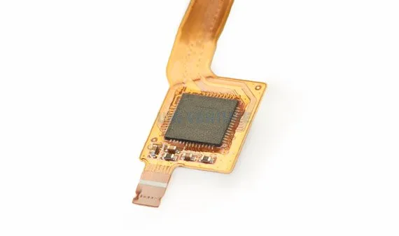
Flex Plus Professional Flex PCB refers to an advanced FPC architecture optimized for hearing aids, representing a specialized flexible PCB application in compact medical electronics. It combines high-density interconnects with mechanical flexibility and supports multi-layer FPCBs where copper traces are laminated between flexible substrates like polyimide, allowing up to eight layers in compact forms without sacrificing bend radius performance. Rigid-flex FPCBs integrate rigid sections for component mounting with flexible tails for dynamic folding, ideal for the ergonomic contours of in-ear devices. Dual-access FPCBs provide component access on both sides of the flex material, maximizing surface utilization in ultra-small footprints. These features address the challenges of integrating microphones, processors, batteries, and speakers into volumes under 1 cubic centimeter. Engineers benefit from Flex Plus by achieving higher circuit density while maintaining electrical performance under repeated flexing.
The relevance of Flex Plus in hearing aids stems from the industry's shift toward completely-in-canal (CIC) and invisible-in-canal (IIC) models, which demand boards smaller than 10mm x 5mm. Traditional rigid PCBs fail here due to their bulk, but Flex Plus FPCs distribute signals efficiently across bends. Compliance with medical standards ensures biocompatibility and durability, critical for devices worn 16 hours daily. Production scalability supports low-volume custom runs for prototyping and high-volume for market deployment. Overall, Flex Plus empowers engineers to push miniaturization limits without compromising on functionality or reliability.
Technical Principles of Multi-Layer FPCBs in Hearing Aids
Multi-layer FPCBs in Flex Plus designs stack conductive layers separated by dielectric films, enabling complex routing for analog audio paths and digital signal processing. Polyimide films provide the base substrate due to their thermal stability up to 200 degrees Celsius and low moisture absorption, preventing delamination during assembly reflow. Adhesive bonding or adhesiveless lamination techniques secure layers, with coverlays protecting traces from environmental exposure. Engineers must calculate bend radii based on layer count and trace width to avoid cracking, typically maintaining a minimum of three times the board thickness. Vias and blind vias interconnect layers, supporting fine-pitch components like 0201 resistors and QFN packages common in hearing aids. Signal integrity remains paramount, as multi-layer stacks minimize crosstalk in high-frequency audio signals up to 20kHz.
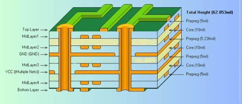
Fabrication begins with photolithography to pattern copper foils, followed by sequential lamination for multi-layer builds. Covercoat application ensures insulation and solder mask functions, while outline routing defines flex zones. Testing verifies continuity and insulation resistance per IPC-6013 standards for flexible PCBs. These principles allow Flex Plus multi-layer FPCBs to handle mixed-signal environments, isolating sensitive analog front-ends from digital noise. Engineers can model electromagnetic interference using field solvers to optimize ground planes across layers.
Integrating Rigid-Flex FPCBs for Enhanced Structural Integrity
Rigid-flex FPCBs combine rigid FR-4 cores with flexible polyimide sections, providing mechanical stability for heavy components like batteries while allowing flex tails for earpiece connections. In Flex Plus hearing aid designs, the rigid portion hosts the main processor and capacitors, transitioning seamlessly to flex for volume-constrained areas. ZIF connectors at flex-rigid interfaces facilitate assembly, reducing solder joints prone to fatigue. Material matching prevents thermal expansion mismatches during operation, as hearing aids experience body temperature fluctuations. Engineers design overlap zones with controlled copper plating to distribute stresses evenly. This hybrid approach extends board life beyond 10 years, aligning with device replacement cycles.
Manufacturing rigid-flex FPCBs involves bookbinding lamination, where rigid and flex sections are stacked and etched together. Fiducials ensure alignment during sequential processing, critical for high-layer counts. IPC-6013 guidelines dictate qualification tests like cyclic flexing and thermal shock to validate performance. Flex Plus rigid-flex variants excel in dual-access configurations, mounting SMDs on both rigid faces. Practical benefits include reduced overall assembly height, enabling sleeker hearing aid profiles.

Dual-Access FPCBs: Maximizing Component Density
Dual-access FPCBs expose both sides of the flexible substrate for component population, doubling usable area in space-limited hearing aids. Engineers apply solder paste through stencils on top and bottom, using selective fiducials for pick-and-place accuracy. This design suits symmetric layouts, such as placing amplifiers on one side and filters on the other, connected via through-holes. Challenges include warpage control during reflow, mitigated by symmetric copper balancing. Coverlays on non-component areas protect traces while allowing access windows precisely aligned. Flex Plus dual-access FPCBs support pitches down to 0.2mm, accommodating the latest DSP chips.
Assembly requires low-temperature solders to preserve flex integrity, followed by underfill for mechanical reinforcement. IPC-A-600 acceptability criteria guide visual inspections for defects like bridging or opens. In hearing aids, dual-access reduces board length by 30 percent compared to single-sided, critical for IIC models. Engineers troubleshoot via X-ray for hidden joints, ensuring void-free connections.
Best Practices for Manufacturing Flex Plus FPCs under ISO 13485:2016
ISO 13485:2016 mandates risk-based quality management for medical device components, including Flex Plus FPCs for hearing aids. Processes start with supplier qualification for materials like polyimide and copper foil, ensuring traceability via lot codes. Cleanroom handling prevents contamination, with ESD controls protecting sensitive circuits. Automated optical inspection (AOI) verifies trace integrity post-etching, complemented by flying probe for electrical testing. Engineers implement design for manufacturability (DFM) reviews, specifying bend allowances and stiffeners early. Validation runs confirm yields above 95 percent before full production.

Sustainability practices integrate with ISO 13485:2016 by recycling etchants and minimizing waste in panel utilization. Final packaging uses moisture-barrier bags per JEDEC J-STD-020 for storage. Documentation includes process flowcharts and failure mode effects analysis (FMEA) for continuous improvement. These practices ensure Flex Plus FPCs meet regulatory scrutiny while delivering consistent performance.
Troubleshooting Common Issues in Hearing Aid FPC Designs
Electronic engineers often encounter signal loss in flex zones due to trace cracking from excessive bending. Mitigation involves reinforcing traces with wider paths or parallel routing in high-stress areas. Moisture ingress causes corrosion in multi-layer FPCBs, addressed by conformal coatings compliant with biocompatibility tests. Component shift during flexing affects dual-access boards, resolved by anchoring with epoxy dots. Thermal management challenges arise from battery proximity, necessitating copper pours for heat spreading. Systematic root cause analysis using IPC-6013 test protocols identifies fixes efficiently.
Rigid-flex transitions fail under vibration, common in active lifestyle hearing aids. Adding strain relief vias distributes loads effectively. Yield drops in high-layer counts stem from lamination voids, prevented by vacuum pressing. Engineers log data in controlled databases per ISO 13485:2016 for trend analysis.
Conclusion
Flex Plus Professional Flex PCB for hearing aids integrates multi-layer FPCBs, rigid-flex FPCBs, and dual-access FPCBs to achieve unparalleled miniaturization and reliability. Engineers leverage these technologies to design devices that fit seamlessly while processing audio with precision. Adherence to ISO 13485:2016 and IPC-6013 ensures manufacturing excellence from prototype to production. Key practices like DFM, rigorous testing, and material optimization drive success. As hearing aid technology advances, Flex Plus remains a cornerstone for innovative, patient-centric solutions. Prioritizing these principles positions designs for regulatory approval and market leadership.
FAQs
Q1: What are the main advantages of multi-layer FPCBs in Flex Plus hearing aids?
A1: Multi-layer FPCBs enable dense routing for mixed-signal circuits, reducing board size while maintaining signal integrity. They support fine-pitch components essential for compact processors and amplifiers. Polyimide substrates withstand repeated flexing without delamination. Compliance with IPC-6013 ensures performance under thermal and mechanical stress. Engineers gain flexibility in layout for CIC designs.
Q2: How do rigid-flex FPCBs improve hearing aid durability?
A2: Rigid-flex FPCBs provide stable mounting for batteries and ICs in rigid sections, with flexible tails conforming to ear shapes. This hybrid reduces solder joint fatigue in dynamic environments. Strain relief at interfaces prevents cracks during use. ISO 13485:2016 processes validate long-term reliability. Ideal for dual-access applications maximizing space.
Q3: What makes dual-access FPCBs suitable for electronic engineers in hearing aids?
A3: Dual-access FPCBs allow components on both sides, doubling density in ultra-small footprints. Precise stencil printing and underfill secure assemblies. They minimize board length for IIC models. Troubleshooting focuses on warpage via symmetric designs. Flex Plus variants excel under IPC-A-600 inspection criteria.
Q4: Why is ISO 13485:2016 critical for Flex Plus FPC manufacturing?
A4: ISO 13485:2016 establishes risk-managed quality systems for medical FPCs, ensuring traceability and contamination control. It covers validation from material to final test. Cleanroom protocols protect biocompatibility. Engineers rely on it for regulatory compliance in hearing aids.
References
IPC-6013E — Qualification and Performance Specification for Flexible and Rigid-Flex Printed Boards. IPC, 2020
IPC-A-600K — Acceptability of Electronic Assemblies. IPC, 2020
ISO 13485:2016 — Medical Devices Quality Management Systems. ISO, 2016
JEDEC J-STD-020E — Handling, Packing, Shipping, and Use of Moisture/Reflow Sensitive Surface Mount Devices. JEDEC, 2014


