Introduction
Virtual reality headsets pack dense electronics into compact enclosures, where processors, displays, and sensors generate significant heat. Effective VR headset PCB heat dissipation becomes critical to prevent overheating, which can degrade performance and user comfort during extended sessions. Engineers face unique challenges due to the wearable nature of these devices, demanding lightweight yet robust thermal solutions. PCB thermal analysis VR helps identify hotspots early, ensuring reliability under high workloads. This article explores structured approaches to optimize thermal management, focusing on practical engineering principles for electric engineers designing next-generation VR systems. By prioritizing heat transfer efficiency, designers can enhance device longevity and immersion quality.
Why Thermal Management Matters in VR Headset PCBs
VR headsets integrate high-power system-on-chips, graphics processors, inertial measurement units, and OLED displays, all contributing to elevated junction temperatures. Poor heat dissipation leads to thermal throttling, where components reduce clock speeds to avoid failure, compromising frame rates and responsiveness. In a confined headset volume, accumulated heat also raises surface temperatures, causing user discomfort or skin irritation during prolonged use. Reliability issues arise from thermal cycling, which induces stresses per IPC-2221 guidelines on material expansion mismatches. VR PCB cooling solutions directly impact battery life, as excessive heat accelerates chemical degradation in power sources. Ultimately, robust thermal design aligns with performance specifications, enabling sustained operation in dynamic environments like gaming or training simulations.
Fundamental Thermal Principles in VR Headset PCB Design
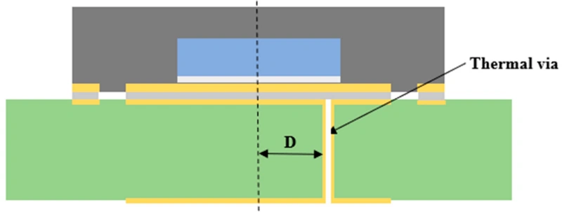
Heat in PCBs transfers primarily through conduction along copper traces and planes, convection via air or forced flow, and minor radiation effects. Key metrics include thermal resistance, measured in degrees Celsius per watt, which quantifies a path's heat-blocking potential. In VR applications, multilayer stackups amplify conduction challenges, as inner layers trap heat from surface-mounted power devices. Thermal vias serve as vertical conduits, bridging top-side hotspots to bottom planes or embedded heat spreaders. Engineers must balance via density with fabrication limits to minimize resistance without compromising signal integrity. Understanding these mechanisms forms the basis for effective VR headset PCB heat dissipation strategies.
Copper pour areas act as heat spreaders, distributing localized power dissipation across larger surfaces for improved convection. Plane thickness influences spreading impedance, with thicker copper reducing gradients. Material selection plays a role, favoring laminates with higher glass transition temperatures to withstand VR operational peaks. Per JEDEC thermal characterization standards, accurate modeling requires boundary conditions reflecting real-world airflow around headsets. Radiation contributes minimally in enclosed spaces but gains relevance with metallic chassis. These principles guide iterative refinements in PCB layout for optimal thermal gradients.
PCB Thermal Analysis and Simulation for VR Headsets
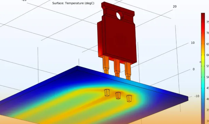
PCB thermal analysis VR employs finite element analysis to map temperature distributions under load conditions. Engineers simulate power dissipation from components, accounting for stackup, vias, and enclosure interactions. Thermal simulation VR headset PCB reveals hotspots near processors, informing via placement and plane sizing. Convergence criteria ensure model accuracy, typically targeting less than 1 degree Celsius variation between iterations. Boundary conditions mimic headset ventilation, such as passive slots or micro-fans, to predict real-world behavior. Validation against prototypes confirms simulation fidelity, reducing physical iterations.
Multiphysics coupling integrates electrical current with thermal fields, per IPC-2221 thermal management sections. Current-induced Joule heating in traces emerges as a secondary source in high-speed VR interfaces. Sensitivity studies vary parameters like via diameter or fill factor to optimize designs. Post-processing extracts metrics such as maximum junction temperature and thermal gradients. For VR, simulations prioritize lightweight solutions avoiding bulky heatsinks. This analytical approach accelerates development cycles while upholding reliability margins.
Practical Solutions for VR Headset PCB Heat Dissipation
Thermal vias for VR PCB rank among the most effective techniques, arrayed under high-power IC thermal pads to channel heat downward. Optimal via sizing balances thermal conductance with drilling costs, typically 0.3 to 0.5 mm diameter in 1.6 mm boards. Filling vias with conductive epoxy enhances performance by 20 to 50 percent over air-filled, though tenting prevents solder wicking during assembly. Arrays of 9 to 25 vias per pad suit VR processor footprints, connected to full copper planes via stitched perimeters. Anti-pads around signal vias prevent shorts, maintaining isolation amid dense routing.
VR PCB cooling solutions extend to embedded heat pipes or vapor chambers for extreme densities, interfacing via direct bond copper. Surface treatments like black oxide improve emissivity for radiation, though convection dominates in headsets. Component placement clusters heat sources over vents, leveraging natural chassis airflow. Multilayer planes alternate signal and power layers, maximizing spreading without crosstalk. Hybrid stackups incorporate high-thermal-conductivity cores, bridging dielectrics for through-plane conduction. These methods collectively lower peak temperatures by distributing loads evenly.
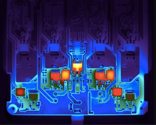
Heatsink integration requires low-profile fins or pin arrays, attached via phase-change materials for minimal thermal interface resistance. Board stiffeners double as spreaders, mitigating warpage from thermal expansion per IPC standards. Ventilation cutouts demand EMI shielding to protect VR wireless modules. Iterative prototyping with infrared thermography validates solutions against simulations. Engineers prioritize passive over active cooling to preserve battery autonomy and acoustics.
Best Practices and Troubleshooting in VR Thermal Design
Position high-dissipation components centrally or near edges with airflow paths, minimizing trace lengths to reduce resistive losses. Stackup planning dedicates inner layers to ground planes, enhancing return paths and shielding. Via fencing around critical areas stitches planes, curtailing lateral heat flow. Fabrication notes specify via plating thickness, typically 1 ounce copper, for durability. Assembly processes incorporate underfill for BGA packages, aiding heat extraction from dense arrays.
Common pitfalls include insufficient via density, leading to pad delamination under thermal stress. Troubleshooting involves dissecting simulation deltas from measurements, often tracing to unmodeled contact resistances. Overly aggressive copper pours can warp thin boards, addressed by symmetric layering. Fan-assisted cooling risks dust accumulation in headsets, favoring passive enhancements. Regular design reviews enforce IPC-2221 compliance on clearances and spacings. Documenting thermal budgets ensures margin for firmware updates or overclocking.
Conclusion
Optimizing thermal management in VR headset PCBs demands a holistic approach, from simulation-driven analysis to via-optimized layouts. Key strategies like thermal vias for VR PCB and copper plane utilization directly tackle heat dissipation challenges in compact form factors. Adhering to standards such as IPC-2221 ensures designs withstand operational rigors. Engineers benefit from early prototyping and iterative refinement to balance performance, weight, and cost. Implementing these practices elevates VR device reliability, user satisfaction, and market viability. Future advancements in materials will further refine these solutions.
FAQs
Q1: What role do thermal vias play in VR headset PCB heat dissipation?
A1: Thermal vias for VR PCB efficiently transfer heat from top-side components to inner planes or chassis, reducing junction temperatures in power-dense areas. Best practices include arrays under IC pads with diameters suited to board thickness, connected via perimeter stitching. Filling enhances conductance, while tenting aids assembly reliability. Simulations guide density to avoid over-drilling costs. This approach aligns with IPC-2221 thermal guidelines for multilayer boards.
Q2: How does PCB thermal analysis VR improve design outcomes?
A2: PCB thermal analysis VR employs FEA to predict hotspots, enabling proactive via and plane adjustments before fabrication. It accounts for VR-specific loads like sustained GPU rendering, incorporating enclosure airflow boundaries. Validation against JEDEC test conditions refines models for accuracy. Engineers iterate on stackups to meet thermal budgets, preventing throttling. Overall, it shortens development and boosts reliability in compact headsets.
Q3: What are effective VR PCB cooling solutions for engineers?
A3: VR PCB cooling solutions prioritize passive methods like copper pours, thermal vias, and high-conductivity laminates to manage heat without added weight. Heatsinks with TIMs interface chassis, while ventilation optimizes convection. Simulations ensure even dissipation, avoiding localized failures. Layout clusters sources over vents, per design standards. These yield sustained performance in wearable VR applications.
Q4: Why is thermal simulation essential for VR headset PCB design?
A4: Thermal simulation VR headset PCB maps full-system temperatures, revealing interactions between components and enclosure. It supports sensitivity analysis on via configurations and materials, optimizing for minimal gradients. Boundary conditions reflect headset ergonomics, like head-induced airflow variations. Compliance with standards like IPC-2221 validates margins. This prevents field failures, ensuring immersive experiences endure long sessions.
References
IPC-2221B — Generic Standard for Printed Board Design. IPC, 2003
IPC-6012E — Qualification and Performance Specification for Rigid Printed Boards. IPC, 2017
JEDEC JESD51-2A — Integrated Circuits Thermal Test Method Environmental Conditions - Natural Convection. JEDEC, 2008


