Introduction
Multilayer printed circuit boards form the backbone of automotive electronics in today's vehicles, supporting everything from advanced driver-assistance systems to electric powertrains. These boards integrate multiple layers of conductive traces and insulating materials to handle complex circuitry in compact spaces. As vehicles incorporate more sensors, processors, and power electronics, the need for robust automotive PCB design grows critical. High-reliability PCBs for automotive must withstand extreme conditions like vibration, temperature swings, and electromagnetic interference. This article explores how multilayer PCBs meet these demands through material choices, design strategies, and compliance with automotive PCB standards. Engineers designing for automotive applications benefit from understanding these principles to ensure long-term performance.
Understanding Multilayer PCBs in Automotive Contexts
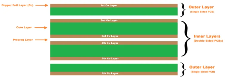
Multilayer PCBs consist of three or more conductive layers bonded together with dielectric materials, enabling high-density interconnections essential for modern automotive systems. In vehicles, these boards manage high-speed data signals for infotainment, radar, and camera modules while powering high-current components in battery management systems. The layered structure reduces overall board size compared to single or double-sided designs, which is vital in space-constrained engine compartments or dashboards. Automotive PCB design requires careful layer stackup to balance signal integrity and mechanical stability. Troubleshooting issues like crosstalk or impedance mismatches often traces back to improper layer sequencing during initial layout. By optimizing via placement and plane assignments, designers achieve reliable operation under dynamic loads.
Key Challenges Facing Automotive Electronics PCBs
Automotive environments expose PCBs to relentless stresses including mechanical shock from road vibrations, thermal cycling from engine heat, and corrosive humidity in underbody locations. High-reliability PCBs for automotive must resist delamination, cracking, or trace fractures that could lead to system failures. Power electronics generate significant heat, complicating thermal management in automotive PCBs and risking component degradation. Electromagnetic compatibility becomes a concern with closely packed high-frequency circuits in ADAS modules. Engineers often troubleshoot warpage issues arising from mismatched coefficients of thermal expansion between layers. Addressing these challenges starts with selecting appropriate PCB materials for automotive that prioritize durability over cost.
Selecting PCB Materials for Automotive Applications
PCB materials for automotive must exhibit high glass transition temperature to endure repeated thermal excursions without softening. FR-4 variants with enhanced mechanical strength serve as baselines, but advanced formulations incorporate fillers for better dimensional stability. Dielectrics with low moisture absorption prevent ionic contamination that accelerates corrosion in humid conditions. Copper foil types influence peel strength, critical for vibration-prone areas. Troubleshooting material-related failures involves verifying compliance with qualification tests for flexure and thermal shock. Layer bonding agents ensure interlayer adhesion, reducing risks of separation during assembly or operation.
Automotive PCB Design Best Practices
Effective automotive PCB design begins with defining a symmetric stackup to minimize warpage during fabrication and reflow. Trace routing prioritizes wide paths for high-current power delivery while maintaining controlled impedance for differential pairs in sensor interfaces. Via strategies, such as staggered blind and buried vias, enhance density without compromising reliability. Ground planes shield sensitive signals from EMI, a common troubleshooting target in noisy automotive settings. Designers simulate signal integrity to preempt timing violations. Integrating test points facilitates in-circuit verification post-assembly.
Thermal Management in Automotive PCBs
Thermal management in automotive PCBs demands proactive strategies to dissipate heat from power ICs and motor drivers. Copper pours and thick inner layers act as heat spreaders, channeling warmth away from hotspots. Thermal vias arrays under hot components transfer heat to opposite layers or external sinks. Material choices with high thermal conductivity augment these features, especially in high-power modules. Troubleshooting overheating often reveals inadequate via density or blocked airflow paths. Engineers model junction temperatures early to validate designs before prototyping.
High-Reliability Features and Manufacturing Processes
High-reliability PCBs for automotive incorporate sequential lamination for complex multilayer builds, ensuring precise registration across layers. Plating processes deliver uniform barrel wall thickness in vias to withstand cyclic stresses. Solder mask and silkscreen applications protect traces from environmental ingress. Baking preconditions boards against popcorning during reflow. Troubleshooting yield losses points to controlled impedance verification during fab. Final inspections confirm annular ring integrity and solderability.
Automotive PCB Standards and Compliance
Automotive PCB standards like IPC-6012DA outline stringent qualification criteria for rigid boards in vehicle applications, covering bow, twist, and conductor spacing. Assembly follows IPC-A-610 Class 3 provisions for visual acceptability under harsh conditions. Soldering adheres to IPC J-STD-001 requirements, with automotive addendums addressing vibration and thermal cycling. These standards guide troubleshooting by defining defect thresholds. Compliance testing includes thermal shock and humidity bias to simulate real-world exposure. Integrating these early prevents costly redesigns.
Troubleshooting Common Issues in Automotive Multilayer PCBs
Vibration-induced microcracks in vias manifest as intermittent connectivity; reinforcing with filled vias resolves this. Delamination from poor adhesion shows in cross-sections; material preconditioning counters it. Signal crosstalk in high-speed layers requires guard traces or stitching vias for mitigation. Overheating in power sections benefits from metal-core integration for direct chassis cooling. Warpage exceeding limits hampers assembly; asymmetric stackups or CTE-matched cores fix it. Systematic failure analysis using microscopy and electrical probing pinpoints root causes efficiently.
Future Directions in Automotive PCB Technology
Emerging electric vehicles push multilayer PCBs toward embedded passives and integrated power modules for efficiency. Flexible-rigid hybrids accommodate curved surfaces in next-gen interiors. Advanced materials promise lower dielectric loss for 5G vehicle-to-everything communications. Design tools evolve to incorporate multiphysics simulations for holistic reliability prediction. Troubleshooting paradigms shift to AI-driven anomaly detection in production data.
Conclusion
Multilayer PCBs stand at the intersection of innovation and reliability in automotive electronics, enabling the smart vehicles of tomorrow. Strategic automotive PCB design, robust PCB materials for automotive, and effective thermal management in automotive PCBs ensure mission-critical performance. Adhering to automotive PCB standards fortifies boards against environmental rigors. Engineers applying these practices troubleshoot proactively, minimizing field failures. As demands intensify, multilayer solutions will evolve to support autonomous driving and electrification seamlessly.
FAQs
Q1: What are the primary considerations in automotive PCB design?
A1: Automotive PCB design prioritizes high-reliability PCBs for automotive by focusing on vibration resistance, thermal dissipation, and EMI shielding. Stackup symmetry prevents warpage, while impedance-controlled traces support high-speed signals. Material selection ensures CTE matching across layers. Troubleshooting emphasizes simulation for signal integrity. Compliance with automotive PCB standards like IPC-6012DA verifies durability.
Q2: How does thermal management in automotive PCBs impact reliability?
A2: Thermal management in automotive PCBs prevents junction overheating in power electronics, extending component life under engine bay conditions. Techniques include thermal vias, copper planes, and high-conductivity dielectrics. Poor management leads to solder joint fatigue, addressable via modeling. Layer thickness aids heat spreading. Integration with chassis cooling enhances overall system stability.
Q3: What role do PCB materials for automotive play in high-reliability applications?
A3: PCB materials for automotive feature high Tg and low moisture uptake to combat thermal cycling and corrosion. They maintain interlayer adhesion during flexure tests. Selection influences warpage and CTE mismatch issues. Troubleshooting involves qualification per IPC standards. Enhanced formulations support denser multilayer builds without reliability trade-offs.
Q4: Which automotive PCB standards are essential for compliance?
A4: Automotive PCB standards such as IPC-6012DA, IPC-A-610, and IPC J-STD-001 define performance for rigid boards and assemblies. They specify tolerances for conductor quality, plating, and solder joints. Class 3 criteria apply for critical functions. Adherence guides manufacturing and troubleshooting. These ensure high-reliability PCBs for automotive endure vehicle stresses.
References
IPC-6012DA - Automotive Applications Addendum to IPC-6012D, Qualification and Performance Specification for Rigid Printed Boards. IPC, 2016
IPC-A-610J - Acceptability of Electronic Assemblies. IPC, 2024
IPC J-STD-001J - Requirements for Soldered Electrical and Electronic Assemblies. IPC, 2024
IPC-4101 - Specification for Base Materials for Rigid and Multilayer Printed Boards. IPC, 2017


