Introduction
Water conservation has become a critical challenge in agriculture and landscaping, where inefficient irrigation leads to substantial waste. Smart irrigation systems address this by using real-time data to optimize water delivery, and PCB-based soil moisture sensors play a pivotal role in providing accurate measurements. These sensors, built on custom printed circuit boards, detect moisture levels through electrical properties of soil, enabling automated adjustments to irrigation schedules. Engineers designing such systems appreciate the integration of sensing elements directly onto PCBs, which reduces size, cost, and power consumption while enhancing reliability in harsh outdoor environments. Key aspects like soil moisture sensor PCB design focus on durability against moisture, temperature fluctuations, and soil contaminants. This article explores the engineering behind low-power PCB for irrigation, wireless soil sensor PCB implementations, capacitive soil moisture sensor PCB techniques, and PCB integration with irrigation systems, offering practical insights for electric engineers.
The demand for these sensors stems from global water scarcity, with agriculture accounting for about 70 percent of freshwater use in many regions. By embedding intelligence at the sensor level via PCBs, systems achieve precision that traditional timers cannot match. Electric engineers must consider factors like signal integrity, power management, and wireless communication when developing these boards. Advances in PCB fabrication allow for compact designs that withstand prolonged exposure to soil, making them ideal for large-scale deployments. Ultimately, these sensors contribute to sustainable practices by minimizing overwatering and runoff.
What Are PCB-Based Soil Moisture Sensors and Why Do They Matter?
PCB-based soil moisture sensors utilize the printed circuit board as both the structural base and the sensing element, distinguishing them from discrete probe designs. In soil moisture sensor PCB design, electrodes or capacitive plates are etched directly onto the board, which interacts with soil to measure dielectric changes caused by water content. This approach simplifies assembly, lowers material costs, and improves calibration accuracy compared to off-board sensors. For electric engineers, the relevance lies in their ability to enable closed-loop irrigation control, where sensor data triggers solenoid valves or pumps precisely.
These sensors matter because they support water conservation at scale, potentially reducing usage by 20 to 50 percent in optimized systems without sacrificing crop yields. In commercial farming or urban green spaces, deploying networks of wireless soil sensor PCBs allows for zoned irrigation based on micro-variations in soil conditions. Engineers value their low maintenance, as robust PCB encapsulation protects against corrosion and mechanical stress. Compliance with standards like IPC-6012E ensures the boards perform reliably under environmental stresses, justifying investment in custom designs. As climate pressures intensify, these sensors become essential for resilient irrigation infrastructure.
Technical Principles of Capacitive Soil Moisture Sensors on PCBs
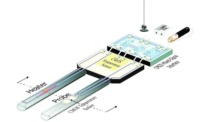
Capacitive soil moisture sensor PCB designs rely on the principle that water has a high dielectric constant, around 80, compared to dry soil's value of 3 to 5. When a PCB with interdigital or parallel plate electrodes is inserted into soil, moisture alters the capacitance between traces, which a microcontroller measures via charge time or frequency shift. This non-contact method avoids corrosion issues plaguing resistive sensors, as no current flows through the soil. Electric engineers optimize trace geometry, gap widths, and substrate materials to achieve linear response over a wide moisture range, typically 0 to 100 percent volumetric water content.
The PCB substrate, often with low moisture absorption, serves as the capacitor dielectric when coated appropriately. Signal conditioning circuits on the board amplify and filter the weak capacitance changes, converting them to digital values via ADC channels. Temperature compensation is crucial, as soil thermal variations affect readings, so thermistors integrated on the PCB provide correction data. Low-power operation is achieved through duty-cycled measurements, where the sensor wakes periodically to sample and transmit. This design minimizes energy draw, critical for battery or solar-powered deployments in remote fields.
Wireless soil sensor PCB variants incorporate RF transceivers for data transmission over distances up to several kilometers in open areas. Modulation schemes like spread-spectrum ensure robust communication amid soil interference. Antenna tuning on the PCB matches impedance for efficient power use, while shielding prevents EMI from affecting sensor accuracy. These principles enable scalable networks where multiple nodes report to a central controller.
Designing Low-Power PCBs for Irrigation Applications
Low-power PCB for irrigation demands meticulous power budgeting, starting with component selection for ultra-low quiescent currents. Microcontrollers with sleep modes drawing microamps dominate the design, paired with voltage regulators boasting high efficiency at light loads. Engineers calculate total average power by factoring measurement intervals, typically every 15 to 60 minutes, against transmission bursts. Energy harvesting options, such as small solar cells connected via MPPT circuits on the PCB, extend operational life indefinitely in sunny climates.
PCB layout plays a key role in minimizing parasitic losses; ground planes reduce noise, and short traces for power distribution cut IR drops. Decoupling capacitors near ICs stabilize supplies during active periods. For soil exposure, conformal coatings per IPC-A-600K criteria protect against humidity ingress, preserving low-power performance. Firmware optimizes algorithms, like adaptive sampling rates based on moisture stability, further conserving energy.
Battery management includes low-voltage cutoffs to prevent deep discharge, integrated via comparators on the PCB. Testing involves long-term bench simulations of soil cycles to validate power models. These strategies ensure wireless soil sensor PCBs operate for years without replacement, aligning with sustainable irrigation goals.
PCB Integration with Irrigation Systems
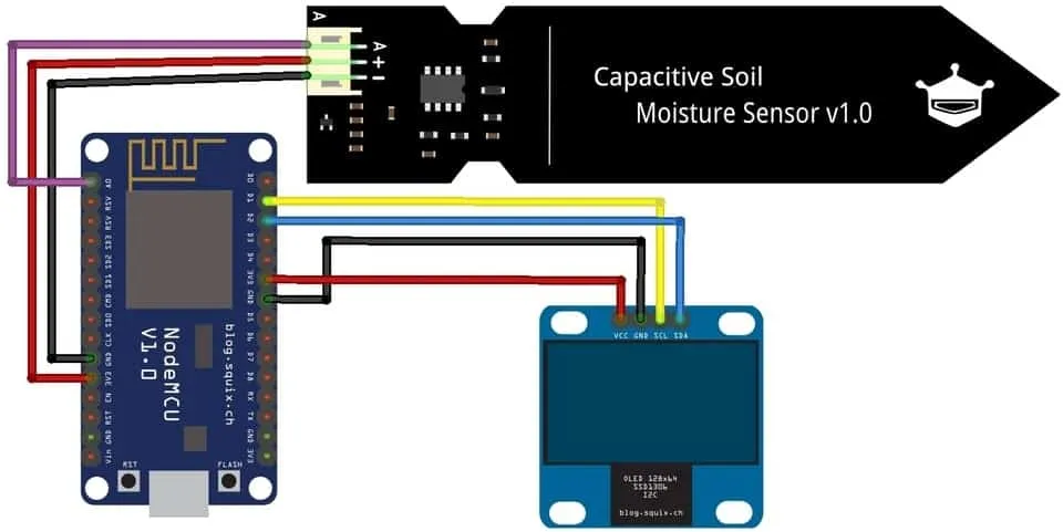
PCB integration with irrigation systems involves interfacing sensors to controllers via wired or wireless protocols, ensuring seamless data flow for automated decisions. In a typical setup, sensor PCBs output serialized data packets containing moisture, temperature, and battery status, received by a gateway or hub. Electric engineers design protocols with checksums for error detection in noisy environments. Threshold-based logic on the controller actuates valves when moisture falls below setpoints, calibrated per soil type.
For scalability, mesh networking on wireless soil sensor PCBs allows node-to-node relaying, extending range without infrastructure. Gateways aggregate data for cloud uplink, though edge processing on sensors reduces latency for immediate valve control. Power-line communication offers wired alternatives for fixed installations, overlaying sensor signals on existing irrigation cabling. Robustness comes from galvanic isolation where AC lines meet low-voltage sensor circuits, preventing ground loops.
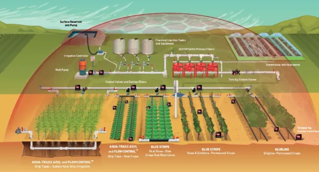
Challenges like signal attenuation in dense foliage require diversity antennas or frequency hopping in the PCB design. Firmware over-the-air updates enable field tweaks without physical access. Overall, tight integration yields systems responsive to real-time conditions, maximizing water efficiency.
Best Practices and Common Challenges in Deployment
When implementing soil moisture sensor PCB design, engineers prioritize environmental protection through potting compounds or IP67-rated enclosures, shielding PCBs from abrasion and chemicals. Calibration curves, derived from lab soil tests, are stored in non-volatile memory for on-board linearization. Multi-sensor fusion, combining capacitive data with salinity compensation, enhances accuracy in varying soils.
Assembly follows J-STD-001 requirements for soldering quality, ensuring reliable joints under vibration. Field troubleshooting involves diagnostic LEDs or serial debug pins on the PCB for quick fault isolation. Common issues like drift from biofouling are mitigated by periodic air calibrations or disposable probe tips.
Periodic validation against reference sensors maintains system trust. These practices, grounded in standards, deliver long-term reliability.
Conclusion
PCB-based soil moisture sensors revolutionize smart irrigation by delivering precise, low-power monitoring essential for water conservation. From capacitive soil moisture sensor PCB principles to wireless soil sensor PCB networks and PCB integration with irrigation systems, engineers have robust tools to build efficient solutions. Adhering to standards like IPC-6012E and J-STD-001 ensures performance in demanding conditions. Low-power PCB for irrigation designs extend deployment viability, reducing operational costs. As water resources dwindle, these technologies empower sustainable agriculture, offering electric engineers opportunities to innovate at the intersection of electronics and environmental stewardship.
FAQs
Q1: What key considerations define effective soil moisture sensor PCB design?
A1: Soil moisture sensor PCB design emphasizes capacitive electrode patterns for accurate dielectric measurement, low-noise layouts for signal integrity, and moisture-resistant substrates. Engineers focus on trace spacing to match soil probe depths, integrating ADCs and MCUs for processing. Conformal coatings protect against corrosion, while standards like IPC-6012E guide qualification. Power optimization via sleep modes supports long-term field use.
Q2: How does a low-power PCB for irrigation achieve extended battery life?
A2: A low-power PCB for irrigation uses components with microamp sleep currents, duty-cycled sampling, and efficient regulators. Firmware adapts measurement frequency based on soil stability, minimizing active time. Solar integration via PCB-mounted panels supplements batteries. Ground planes and decoupling reduce losses, enabling years of operation without recharge.
Q3: What role does wireless soil sensor PCB play in large-scale systems?
A3: Wireless soil sensor PCB enables distributed networks for zoned irrigation, transmitting moisture data over RF to central controllers. Mesh topologies extend coverage, with protocol checksums ensuring reliability. Antenna integration on the board optimizes range, supporting PCB integration with irrigation systems for automated control.
Q4: Why prefer capacitive soil moisture sensor PCB over resistive types?
A4: Capacitive soil moisture sensor PCB avoids galvanic corrosion by not passing current through soil, offering stable long-term readings. It measures dielectric shifts accurately across soil types, with less sensitivity to salinity. PCB etching allows precise electrode control, simplifying manufacturing and calibration.
References
IPC-6012E — Qualification and Performance Specification for Rigid Printed Boards. IPC, 2017
IPC-A-600K — Acceptability of Printed Boards. IPC, 2020
J-STD-001 — Requirements for Soldered Electrical and Electronic Assemblies. IPC, 2020


