Introduction
Smart sensors have revolutionized home appliances by enabling precise environmental monitoring and control directly through printed circuit boards (PCBs). Integrating temperature sensors into home appliance PCBs ensures ovens maintain exact cooking temperatures, while refrigerators optimize compressor cycles to save energy. Pressure sensors in washing machines accurately detect load volumes for efficient water usage, and humidity sensors in air conditioners prevent mold growth by regulating moisture levels. Light sensors enhance user interfaces by auto-adjusting brightness on control panels. This integration not only boosts appliance performance but also supports smart home connectivity. Electrical engineers must master interfacing with MEMS sensors on home appliance PCBs to design reliable systems that meet demanding operational requirements.
Why Sensor Integration Matters for Home Appliance PCBs
Home appliances operate in harsh environments with varying temperatures, humidity, and mechanical stresses, making robust sensor integration essential for longevity and safety. Sensors provide real-time data that microcontrollers use to automate functions, reducing energy consumption by up to significant margins through adaptive control. For instance, integrating pressure sensors into home appliance PCBs in dishwashers prevents overflows by monitoring water pressure dynamically. This approach aligns with user demands for intuitive, efficient devices that minimize manual intervention. Moreover, poor integration can lead to false readings or failures, compromising compliance with reliability standards. Engineers benefit from structured integration to enhance overall system intelligence and market competitiveness.
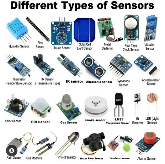
Key Types of Sensors and Their PCB Integration
Temperature sensors are fundamental in appliances like dryers and water heaters, where they convert thermal changes into electrical signals via thermistors or semiconductor ICs. These sensors mount via surface-mount technology (SMT) for compact PCBs, with traces routed to avoid thermal gradients that could skew readings. Integrating temperature sensors into home appliance PCBs requires careful pad sizing per land pattern guidelines to ensure solder joint integrity. Pressure sensors, often MEMS-based, detect force variations in pumps or compressors, outputting analog voltages proportional to applied pressure. Humidity sensors use capacitive elements that change with moisture absorption, ideal for laundry appliances. Light sensors, typically photodiodes, respond to ambient illumination for display backlighting control.
Each sensor type demands specific PCB real estate and via configurations to minimize parasitic effects. Engineers select analog or digital variants based on noise immunity needs, with digital I2C interfaces simplifying multi-sensor buses. Integrating humidity sensors into home appliance PCBs involves shielding capacitive plates from EMI sources like motors. Pressure and light sensors benefit from isolated ground planes to prevent crosstalk. Overall, these integrations transform passive PCBs into active sensing hubs.
Interfacing with MEMS Sensors on Home Appliance PCBs
MEMS sensors combine mechanical and electrical elements at microscale, offering high sensitivity for acceleration, pressure, and gas detection in appliances. Interfacing with MEMS sensors on home appliance PCBs starts with selecting SPI or I2C protocols for low pin-count communication, reducing PCB routing complexity. These sensors often include on-chip ADCs, easing data acquisition by host microcontrollers. Vibration from appliance motors necessitates robust mounting with underfill or conformal coating to prevent delamination. Power supply decoupling capacitors placed near sensor pins stabilize outputs amid supply noise.
Firmware handles sensor fusion, combining MEMS data with other inputs for predictive features like imbalance detection in spin cycles. Electrical engineers must verify interface timing per datasheet specifications to avoid data corruption. Ground bounce mitigation through star grounding enhances signal fidelity. This interfacing elevates appliance intelligence, enabling features like auto-diagnostic routines.
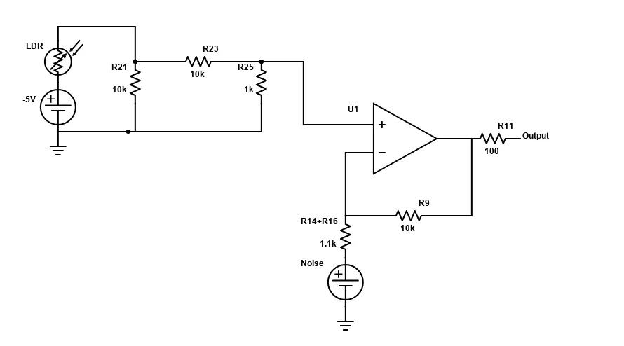
Designing Sensor Signal Conditioning Circuits
Sensor outputs are weak and prone to noise, requiring dedicated signal conditioning circuits on the PCB. Designing sensor signal conditioning circuits involves op-amp based amplifiers for gain adjustment, with feedback resistors selected for bandwidth matching sensor dynamics. Low-pass filters attenuate high-frequency noise from switching regulators, using SMD capacitors and inductors for compact layouts. For ratiometric sensors like temperature types, reference voltages track supply variations, improving accuracy.
Instrumentation amplifiers provide high common-mode rejection for differential pressure signals, crucial in noisy environments. Anti-aliasing filters precede ADCs to prevent spectral folding. PCB layout separates analog and digital sections with split planes, routing sensitive traces as differential pairs. Decoupling and guard rings around op-amps minimize offset drift. These circuits ensure clean signals for precise control algorithms.
Per IPC-A-610 guidelines, solder joints in these dense circuits must exhibit full fillet formation without bridges, ensuring mechanical reliability.
Calibrating Sensors on Home Appliance PCBs
Calibration aligns sensor outputs to true physical values, compensating for offsets, gains, and nonlinearities inherent in manufacturing tolerances. Calibrating sensors on home appliance PCBs occurs during assembly testing, using controlled chambers for temperature and humidity exposure. Multi-point calibration tables store in EEPROM, with firmware applying polynomial corrections during operation. Pressure sensors undergo dead-weight testers to verify linearity across operating ranges.
Temperature compensation curves address thermal drift in humidity sensors, derived from batch characterizations. Light sensors calibrate against standard illuminants to match human perception. Automated in-circuit test equipment applies stimuli via bed-of-nails fixtures, logging data for traceability. Post-calibration verification confirms hysteresis within acceptable bounds. This process upholds performance consistency across production runs.
J-STD-001 requirements guide soldering processes that preserve sensor calibration stability, emphasizing preheat profiles to avoid thermal shock.
Best Practices for Reliable Sensor Integration
Layout sensors away from heat-generating components, using thermal vias for dissipation in multilayer boards. Employ 6-layer stacks for high-density integrations, dedicating inner layers to power distribution. Signal integrity analysis via simulation predicts EMI susceptibility before fabrication. Conformal coatings per IPC standards protect against humidity ingress in washdown appliances.
Testing protocols include thermal cycling and vibration per JEDEC guidelines to validate reliability. Firmware includes watchdog timers for sensor health monitoring. Documentation of stackups and BOMs facilitates revisions. These practices minimize field failures and optimize costs.
Common Challenges and Troubleshooting Insights
Noise coupling plagues analog sensors; isolate with ferrite beads and shield cans. Thermal expansion mismatches cause microcracks in MEMS die attach; select low-CTE adhesives. Drift in humidity sensors from contamination demands sealed enclosures. Troubleshooting starts with oscilloscope captures of raw signals, followed by spectrum analysis.
Firmware debugs via logging reveal interface glitches. Reflow profiling per J-STD-020 prevents moisture-induced pops in hygroscopic sensors. Systematic root-cause analysis resolves intermittents effectively.
Conclusion
Integrating smart sensors into home appliance PCBs unlocks advanced functionality, from energy-efficient operation to enhanced safety. Key strategies include precise interfacing with MEMS sensors, robust signal conditioning, and rigorous calibration. Adhering to standards like IPC-A-610 and J-STD-001 ensures durability in real-world conditions. Electrical engineers can leverage these principles to design next-generation appliances that meet evolving smart home standards. Future trends point toward wireless sensor nodes for even greater flexibility.
FAQs
Q1: How do you integrate temperature sensors into home appliance PCBs effectively?
A1: Position temperature sensors near critical hotspots with dedicated thermal relief pads to avoid solder voids. Use I2C digital variants for multi-sensor daisy-chaining, reducing PCB traces. Implement signal conditioning with precision op-amps for noise rejection. Thermal vias and ground planes stabilize readings. Test via ramped profiles to verify response times. This ensures accurate monitoring in ovens or refrigerators.
Q2: What are the steps for designing sensor signal conditioning circuits on PCBs?
A2: Start with amplifier selection for gain and bandwidth needs, followed by filter design using SPICE simulation. Route traces differentially with matched lengths to preserve integrity. Add decoupling near ICs and split power planes. Verify with bench measurements under load. Per standards, ensure joint quality for reliability. These circuits deliver clean signals for appliance control.
Q3: Why is calibrating sensors on home appliance PCBs critical, and how is it done?
A3: Calibration corrects manufacturing variances, preventing control errors in varying environments. Use environmental chambers for stimuli application, storing lookup tables in flash memory. Perform multi-point checks for linearity and hysteresis. Firmware interpolates for real-time accuracy. In-circuit testers automate the process. This maintains precision in pressure or humidity sensing.
Q4: How does interfacing with MEMS sensors on home appliance PCBs improve appliance design?
A4: MEMS offer compact, low-power sensing for pressure and motion, interfaced via SPI for fast data rates. Robust mounting withstands vibrations. On-chip processing simplifies host burdens. Noise mitigation via filtering enhances reliability. This enables features like predictive maintenance in washers. Engineers achieve denser, smarter PCBs.
References
IPC-A-610H — Acceptability of Electronic Assemblies. IPC, 2019
J-STD-001H — Requirements for Soldered Electrical and Electronic Assemblies. IPC, 2018
J-STD-020E — Moisture/Reflow Sensitivity Classification for Nonhermetic Surface Mount Devices. JEDEC/IPC, 2014


