Introduction
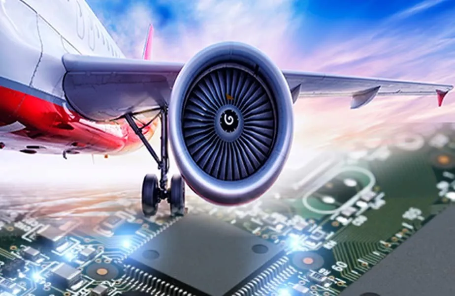
Avionics systems form the backbone of modern aircraft, relying on printed circuit boards (PCBs) to manage critical functions like navigation, communication, and flight control. As aviation evolves toward more electric architectures and autonomous operations, the future of avionics PCBs demands innovations that prioritize reliability, miniaturization, and performance under extreme conditions. Engineers face challenges such as high vibration, temperature fluctuations, and electromagnetic interference, pushing the boundaries of PCB design and manufacturing. Emerging trends like advanced materials, embedded components, flexible designs, and additive processes promise to reshape how these boards integrate into next-generation aircraft. This article explores these developments, offering insights for electrical engineers designing for the skies.
Why Avionics PCBs Matter in Modern Aviation
Avionics PCBs serve as the interconnect foundation for sensors, processors, and actuators in aircraft systems. They must withstand altitudes exceeding 40,000 feet, temperatures from -55°C to over 125°C, and accelerations up to 20g, making reliability non-negotiable. In commercial, military, and unmanned aerial vehicles, these boards enable real-time data processing essential for safety and efficiency. The shift to more electric aircraft reduces hydraulic systems, increasing PCB density and power demands. Future designs will support higher data rates for radar, satellite links, and AI-driven analytics, amplifying the need for robust substrates and interconnects. Without advancements, current limitations in size, weight, and thermal management could hinder aviation progress.
Advanced Materials for Avionics PCBs
Advanced materials address the thermal, mechanical, and electrical demands unique to avionics environments. Traditional FR-4 substrates fall short for high-frequency signals due to higher dielectric loss, prompting the use of low-loss laminates like PTFE-based composites and hydrocarbon ceramics. These materials exhibit lower coefficients of thermal expansion (CTE), minimizing warpage during temperature cycling common in flight operations. Polyimide films provide flexibility and high-temperature stability up to 260°C, ideal for multilayer stacks in engine monitoring systems. Engineers select these based on signal integrity requirements, ensuring impedance control per IPC-6012 standards for rigid boards. As the future of avionics PCBs unfolds, hybrid material stacks will combine rigidity for components with compliance for vibration damping.
Selection involves balancing dielectric constant (Dk) and dissipation factor (Df) for RF performance in radar and communication modules. Materials with Dk below 3.5 reduce signal skew in high-speed differential pairs. Enhanced thermal conductivity aids heat dissipation from power converters without active cooling. Fabrication processes like laser via drilling accommodate finer features in these laminates. Testing verifies compliance through thermal shock and humidity exposure, aligning with industry benchmarks for long-term reliability.
Embedded Components in Avionics PCBs
Embedding passive components like resistors, capacitors, and inductors directly into the PCB substrate revolutionizes avionics design by slashing volume and improving electrical performance. This approach eliminates surface-mount parasitics, enabling shorter signal paths and better high-frequency response critical for fly-by-wire systems. Heat from embedded devices dissipates through the board core, reducing hotspots in dense avionics bays. Manufacturing integrates components via cavity formation, adhesive bonding, and lamination, followed by planarization for subsequent layers. In avionics, this supports system-in-package concepts, where multiple functions stack vertically to meet space constraints.
Engineers consider component tolerance during embedding, as laser trimming adjusts values post-lamination for precision. Reliability testing includes accelerated life cycles simulating 20,000 flight hours. Embedded actives, like thin-film transistors, extend this to mixed-signal processing. The technique aligns with J-STD-001 requirements for soldered assemblies, though embedding shifts focus to interlayer adhesion. Future implementations will embed sensors for structural health monitoring, embedding intelligence into the airframe itself.
Flexible Avionics PCBs
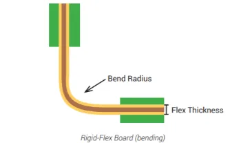
Flexible and rigid-flex avionics PCBs adapt to curved surfaces and dynamic installations, reducing weight by up to 70% compared to wired harnesses. Polyimide substrates enable bending radii as tight as 1mm, routing signals along wings or fuselages without fatigue failure. Rigid sections host processors and connectors, while flex tails interface with sensors, minimizing connectors prone to vibration loosening. High-density interconnects (HDI) in flex areas support data rates beyond 10 Gbps for ethernet avionics networks. Design rules emphasize coverlay thickness and bend alignment to prevent cracking under repeated flexing.
These boards excel in unmanned systems, conforming to irregular drone shapes while maintaining IPC-A-600 acceptability criteria for visual and dimensional quality. Copper ductility in flex layers ensures 100,000+ bend cycles. Shielding integrates via embedded ground planes, mitigating EMI in crowded RF environments. Prototyping validates dynamic flex endurance through cyclic bending tests. As flexible avionics PCBs gain traction, they will enable conformal electronics, wrapping around control surfaces for distributed computing.
3D Printed Avionics PCBs
Additive manufacturing, or 3D printing, emerges as a disruptive force in the future of avionics PCBs, allowing complex geometries unattainable with subtractive etching. Aerosol jet printing deposits conductive inks on non-planar surfaces, creating circuits for conformal antennas or irregular housings. This bypasses photolithography limitations, enabling rapid iteration for custom avionics prototypes. Materials include nanoparticle silver and graphene pastes, sintered for conductivity approaching bulk copper. Multilayer capability builds vias via sequential printing and curing, supporting embedded traces.
Challenges include resolution below 50 microns and adhesion on diverse substrates like composites. Post-processing cures inks at controlled temperatures to match avionics thermal profiles. Qualification involves IPC-6012 conformance for electrical and mechanical integrity. Hybrid approaches combine printed interconnects with traditional SMD for high-rel applications. In the long term, 3D printed avionics PCBs will facilitate on-demand repairs in remote operations, printing patches for damaged boards.
Design Best Practices for Future Avionics PCBs
Engineers should prioritize simulation early, modeling thermal-mechanical stress with finite element analysis to predict warpage. Stackup optimization balances layer count with via density, using blind and buried vias for HDI. Signal integrity tools verify eye diagrams for gigabit serdes links. Material qualification per JEDEC standards ensures moisture resistance. Fabrication partners must demonstrate traceability from raw laminate to final assembly.
Reliability engineering incorporates design for manufacturability (DFM), spacing traces 5 mils minimum in high-voltage areas. Vibration modeling simulates g-forces, guiding anchor point placement. Power integrity analysis prevents droop in more-electric systems. Documentation includes bend allowances for flex and cure profiles for embeds. These practices future-proof designs against evolving certification demands.
Conclusion
The future of avionics PCBs lies in integration: advanced materials enabling high-speed signals, embedded components shrinking footprints, flexible designs conforming to airframes, and 3D printing accelerating innovation. These technologies collectively reduce SWaP (size, weight, and power), vital for next-gen aircraft. Electrical engineers must master interdisciplinary skills, from materials science to additive processes. Adhering to standards like IPC-6012 ensures mission-critical reliability. As aviation electrifies, these trends will propel safer, more efficient flight.
FAQs
Q1: What are the key advanced materials for avionics PCBs?
A1: Advanced materials for avionics PCBs include PTFE laminates for low-loss RF performance and polyimide for high-temperature flexibility. These substrates offer low CTE to match components, reducing stress in thermal cycles. Hydrocarbon ceramics provide stability in humid environments. Selection depends on frequency and power needs, verified through dielectric testing.
Q2: How do embedded components benefit the future of avionics PCBs?
A2: Embedded components in avionics PCBs minimize parasitics, enhancing signal integrity for high-speed data. They improve thermal management by spreading heat across layers and reduce assembly steps. Ideal for dense fly-by-wire systems, they support miniaturization without sacrificing reliability. Design requires precise cavity control during lamination.
Q3: Why choose flexible avionics PCBs for aircraft applications?
A3: Flexible avionics PCBs cut weight and wiring complexity, routing signals to hard-to-reach sensors. Rigid-flex hybrids combine stability for ICs with bendability for installation. They endure vibration per cyclic testing standards. Common in wings and drones, they enable distributed avionics architectures.
Q4: Is 3D printed avionics PCB ready for production use?
A4: 3D printed avionics PCBs excel in prototyping complex shapes via conductive inks. They enable conformal electronics on curved surfaces. Current limits include resolution and conductivity, but hybrids with traditional methods bridge gaps. Standards qualification is progressing for low-volume high-rel applications.
References
IPC-6012DS — Qualification and Performance Specification for Rigid Printed Boards in Space and Military Applications. IPC, 2016
IPC-A-600K — Acceptability of Printed Boards. IPC, 2020
J-STD-001H — Requirements for Soldered Electrical and Electronic Assemblies. IPC, 2020


