Introduction
LED lighting projects often face the challenge of managing heat without breaking the bank. Electronic hobbyists building custom strips, panels, or fixtures need materials that balance performance and cost. CEM-3 emerges as a practical choice for LED PCB material, offering reliable thermal management CEM-3 capabilities at a fraction of premium options. This article explores how CEM-3 PCB thermal conductivity supports efficient heat dissipation in budget-friendly designs. Hobbyists can achieve brighter, longer-lasting LEDs by understanding its strengths in LED lighting PCB design. With simple techniques, even home setups can handle moderate power levels effectively.
What Is CEM-3 and Why It Matters for LED Lighting
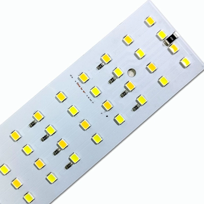
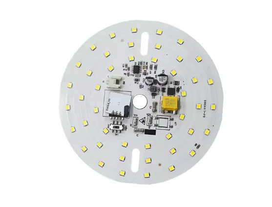
CEM-3 stands for Composite Epoxy Material-3, a laminate combining woven glass fabric with non-woven glass mat and epoxy resin. It serves as a flame-retardant, cost-effective alternative to standard materials, ideal for double-sided boards common in hobbyist LED projects. Unlike paper-based composites, CEM-3 provides better mechanical strength and stability, making it suitable for everyday lighting applications. In LED setups, where heat from drivers and arrays builds up quickly, CEM-3 heat dissipation properties prevent hotspots that shorten component life. Hobbyists appreciate its milky white appearance and smooth drillability, which simplify prototyping.
The relevance grows in budget thermal management, as CEM-3 handles moderate currents without exotic substrates. For indoor fixtures or decorative lights, it outperforms basic phenolics while keeping costs low. Standards like IPC-4101 define its base material specs, ensuring consistency across suppliers. This reliability lets hobbyists focus on creativity rather than material failures.
Understanding Thermal Principles in CEM-3 PCBs
Heat in LED lighting originates from junction temperatures in the diodes and power losses in traces or drivers. CEM-3 PCB thermal conductivity facilitates transfer through its composite structure, spreading warmth across the board before it escapes via copper or air. The material's epoxy matrix and glass reinforcement create pathways that rival common laminates in z-axis conduction, crucial for bottom-mounted heatsinks. In practice, this means LEDs stay cooler during extended operation, reducing color shifts or efficiency drops.
Key mechanisms include in-plane conduction along fibers and through-plane via the resin. While not matching metal cores, CEM-3 suffices for powers under a few watts per chip, common in hobby projects. Designers leverage thick copper layers to boost this effect, turning the board into a passive spreader. Adhering to IPC-6012 performance specs guarantees the board withstands thermal cycling without delamination.
Warpage control matters too, as uneven cooling stresses solder joints. CEM-3's balanced construction minimizes this, per industry test methods. Hobbyists notice fewer failures in prototypes compared to cheaper singlesides.
Practical Solutions for CEM-3 Heat Dissipation in LED Designs
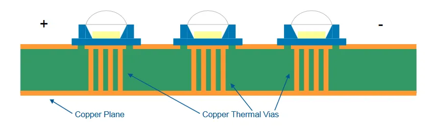
Start with layout basics: place LEDs and drivers close together on one side, using the second for ground planes. Wide traces, at least 1mm per amp, channel current without excessive resistance heating. A full copper pour under LEDs acts as an integrated heatsink, enhancing CEM-3 heat dissipation. Add thermal vias, 0.3mm holes filled or tented, arrayed in 1-2mm grids to wick heat downward.
Thicker copper, like 2oz, multiplies conduction capacity without much cost hike. For strips, serpentine routing prevents bottlenecks. Hobbyists can simulate roughly by hand: estimate power, assume 20-30C/W junction-to-board, and verify with a thermometer. Pair with aluminum profiles clipped on, transferring board heat to ambient.
In multilayer attempts, though rare for budget CEM-3, inner planes further aid. Solder mask thinning over hot zones exposes copper for convection. Troubleshooting hotspots? Check via density first, then airflow baffles from cardboard prototypes.
Assembly tips include low-temp reflow to avoid resin softening, aligning with J-STD-020 guidelines. Post-solder, silicone pads bridge to enclosures. These steps make thermal management CEM-3 straightforward for garage builds.
Troubleshooting Common Issues in Budget LED PCB Designs
Overheating often stems from undersized planes or poor via placement. Measure junction temps with IR guns; above 80C signals redesign. CEM-3 warpage from asymmetric copper? Balance pours across layers. Solder bridges on dense arrays? Larger pads and flux cleanup fix it.
Flickering from thermal runaway? Stabilize drivers with decoupling caps near ICs. Humidity causing creepage? conformal coat selectively. Hobbyists iterate fast: breadboard power first, then PCB. Log failures to refine future boards.
Conclusion
CEM-3 delivers accessible thermal management on a budget, perfect for electronic hobbyists tackling LED lighting. Its CEM-3 PCB thermal conductivity and LED PCB material strengths support reliable heat dissipation without premium pricing. By applying layout tricks, vias, and copper wisely, projects shine longer and brighter. Standards ensure quality, while practical tweaks handle real-world quirks. Experiment confidently; CEM-3 empowers cost-smart innovation in LED lighting PCB design.
FAQs
Q1: What is CEM-3 PCB thermal conductivity compared to standard materials?
A1: CEM-3 offers thermal conductivity suitable for moderate LED loads, often matching or exceeding basic epoxy laminates in practical dissipation. It excels in budget thermal management CEM-3 by spreading heat evenly via its glass-epoxy composite. Hobbyists find it adequate for 1-5W arrays, avoiding metal substrates. Pair with vias for best results in LED PCB material choices.
Q2: How does CEM-3 heat dissipation benefit LED lighting PCB design?
A2: CEM-3 heat dissipation prevents LED degradation in cost-sensitive projects through efficient conduction paths. Use ground planes and thick traces to maximize this in hobby setups. It handles driver heat well, extending fixture life. Troubleshoot by adding airflow if needed.
Q3: Why choose CEM-3 for thermal management CEM-3 in hobby LED projects?
A3: CEM-3 provides a budget-friendly LED PCB material with flame-retardant stability for double-sided boards. Its properties support thermal management CEM-3 without complex stacks. Ideal for strips or panels under 10W total. Standards like IPC-4101 back its reliability.
Q4: Can CEM-3 handle high-power LEDs in PCB designs?
A4: For low-to-medium power, yes; CEM-3 PCB thermal conductivity works with enhancements like vias and heatsinks. Beyond 5W per zone, consider hybrids. Hobbyists succeed by derating and monitoring temps.
References
IPC-4101E — Specification for Base Materials for Rigid and Multilayer Printed Boards. IPC, 2017
IPC-6012E — Qualification and Performance Specification for Rigid Printed Boards. IPC, 2018
J-STD-020E — Moisture/Reflow Sensitivity Classification for Nonhermetic Surface Mount Devices. JEDEC, 2014


