Introduction
Avionics system PCBs form the backbone of aircraft electronics, controlling everything from navigation to communication systems. These boards operate in extreme environments, including rapid temperature changes, high vibration, and electromagnetic interference, making reliability paramount for flight safety. Common avionics PCB problems like solder joint cracks or delamination can lead to intermittent failures with catastrophic potential. Effective avionics PCB troubleshooting starts with systematic diagnosis to pinpoint root causes quickly. This article provides electric engineers with practical guidance on avionics PCB failure analysis, testing avionics PCB assemblies, and repair strategies. By following structured approaches, engineers can minimize downtime and enhance system integrity.
Why Avionics PCBs Require Specialized Troubleshooting
Avionics PCBs must withstand conditions far beyond consumer electronics, such as altitudes exceeding 50,000 feet, temperatures from -55°C to over 125°C, and continuous vibration profiles. These stressors accelerate wear on materials and joints, leading to failures that standard PCBs rarely encounter. Compliance with high-reliability specifications, like IPC-6012DS for rigid printed boards in demanding applications, ensures boards meet performance thresholds under such duress. Troubleshooting matters because early detection prevents in-flight issues, reduces certification delays, and cuts repair costs. Engineers focusing on avionics PCB repair gain confidence through repeatable diagnostics tailored to aerospace demands. Ultimately, rigorous processes align with safety regulations and extend service life.
Common Causes of Failures in Avionics System PCBs
Solder Joint Failures
Solder joints in avionics PCBs often fail due to thermal cycling, where expansion mismatches between components and the board create cracks. Vibration exacerbates this, causing fatigue over thousands of cycles. Symptoms include intermittent connectivity, observed as high resistance during powered tests. Contamination from flux residues can promote electromigration, worsening joint integrity. Poor reflow profiles during assembly lead to cold joints or voids, detectable via visual cues like dull appearances. Addressing these requires understanding material interactions under avionics stresses.
Via and Plating Defects
Vias connecting layers fail from plating voids or barrel cracks, especially in high-density interconnects common in avionics. Barrel cracking arises from z-axis expansion during thermal shocks, compromising signal paths. Symptoms manifest as open circuits or increased insertion loss in high-frequency signals. Manufacturing inconsistencies, like uneven copper plating, accelerate under mechanical shock. Engineers spot these during continuity checks or signal integrity scans. Proper design margins per industry guidelines prevent propagation.
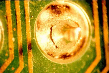
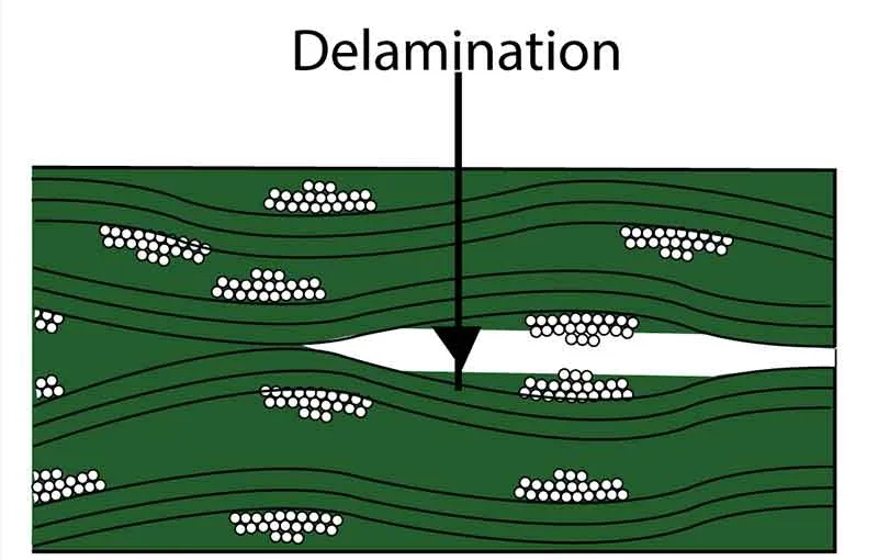
Delamination and Warpage
Delamination occurs when adhesive layers separate due to moisture absorption followed by high-temperature exposure, common in humid storage before avionics integration. Warpage results from asymmetric copper distribution or baking imbalances, stressing components during vibration. These issues cause trace lifts or misalignment, leading to shorts or opens. Symptoms include bulging surfaces or non-planar boards affecting conformal coating adhesion. Thermal history analysis reveals mismatches in coefficients of thermal expansion. Mitigation involves controlled baking and handling protocols.
Contamination and Corrosion
Ionic contaminants from incomplete cleaning promote dendritic growth under bias voltage, a frequent avionics PCB problem in humid cabins. Corrosion attacks exposed copper, especially at edge connectors exposed to salt-laden air. Symptoms are leakage currents or erratic analog readings. Residues from no-clean fluxes exacerbate this in enclosed avionics boxes. Detection via resistivity testing confirms paths. Cleanliness standards guide prevention during avionics PCB assembly.
Mechanical Damage from Vibration and Shock
Avionics environments impose sinusoidal and random vibrations up to 20g, cracking traces or lifting pads over time. Shock from landings fatigues microvias, causing opens. Flexible traces may fatigue at bends, while rigid sections propagate cracks. Symptoms appear as noise spikes or dropouts in data logs. Strain gauging simulates field conditions for prediction. Design reinforcements like wider traces help endure these loads.
Thermal Management and Signal Integrity Issues
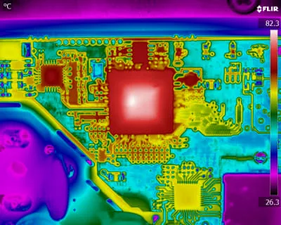
Overheating from poor heat sinking leads to component degradation, with hotspots visible via infrared scans. Signal integrity suffers from crosstalk or reflections in high-speed avionics buses, worsened by impedance mismatches. EMI coupling induces noise in sensitive channels. Symptoms include bit errors or false triggers. Controlled impedance verification during testing avionics PCB layouts is essential. Layer stackup optimization addresses root causes.
Essential Testing Methods for Avionics PCB Troubleshooting
Begin avionics PCB troubleshooting with unpowered visual inspection for obvious defects like lifted pads or discoloration. Magnification reveals solder fillet issues per IPC-A-610 acceptability criteria. Next, perform continuity and short testing using flying probe or bed-of-nails fixtures to map opens and shorts efficiently. Insulation resistance and dielectric withstand tests detect contamination paths under high voltage. Automated optical inspection (AOI) scans for component placement and solder defects rapidly.
For deeper avionics PCB failure analysis, employ X-ray inspection to view hidden vias and barrels without disassembly. Functional circuit testing simulates operational conditions, including vibration tables for mechanical validation. Thermal cycling chambers replicate environmental stresses, revealing latent weaknesses. Advanced techniques like scanning electron microscopy (SEM) analyze fracture surfaces for fatigue striations. Acoustic microscopy detects delamination voids non-destructively. Document all findings to trace back to design or process origins.
Best Practices for Avionics PCB Repair and Prevention
Repair starts with fault isolation, using schematics and data logs to narrow scopes. Clean contaminated areas with isopropyl alcohol, followed by ionic residue testing. Rework solder joints with precise hot air stations, ensuring fillet formation meets criteria. Replace damaged components promptly, verifying pinouts under magnification. Bake boards pre-repair to remove moisture, avoiding popcorn effects. Post-repair, conduct full retesting including burn-in for latent defects.
Prevent future issues through design for testability, like boundary scan access. Select materials with low CTE for vibration resistance. Implement handling ESD protocols and controlled storage. Regular fleet monitoring via health usage data predicts failures. Training on J-STD-001 soldering standards ensures consistent avionics PCB repair quality. These steps build robust systems.
Step-by-Step Troubleshooting Workflow
- Gather symptoms from system logs and replicate failure modes safely.
- Visual and basic electrical checks to isolate board-level issues.
- Advanced non-destructive tests like X-ray and thermal imaging.
- Destructive analysis if needed, sectioning samples.
- Root cause determination and corrective actions.
- Verification testing under simulated avionics conditions.
This workflow streamlines avionics PCB troubleshooting, saving time and resources.
Conclusion
Diagnosing common avionics PCB problems demands a blend of visual, electrical, and environmental testing tailored to harsh flight conditions. Key failures like solder cracks, delamination, and vibration damage require prompt avionics PCB failure analysis to maintain airworthiness. By adhering to standards and methodical practices, engineers achieve reliable repairs and prevent recurrences. Proactive testing avionics PCB assemblies enhances overall system resilience. Implementing these tips ensures safer, more dependable avionics performance.
FAQs
Q1: What are the most common avionics PCB problems electric engineers encounter?
A1: Common avionics PCB problems include solder joint fatigue from vibration, via barrel cracking, and delamination from thermal cycling. Contamination leads to corrosion, while warpage stresses components. Symptoms range from intermittent signals to total opens. Early visual and continuity checks aid diagnosis. Addressing these through structured avionics PCB troubleshooting prevents escalation. (62 words)
Q2: How do you perform avionics PCB failure analysis effectively?
A2: Avionics PCB failure analysis begins with non-destructive methods like X-ray for hidden defects and AOI for surface issues. Electrical tests confirm shorts or high resistance. SEM and cross-sectioning reveal microstructures. Correlate findings with environmental history. Standards guide acceptability. This systematic approach identifies root causes accurately. (58 words)
Q3: What testing methods are best for avionics PCB troubleshooting?
A3: Testing avionics PCB involves visual inspection, flying probe for continuity, and functional tests under vibration. Hi-pot verifies insulation, while thermal imaging spots hotspots. X-ray inspects vias non-destructively. Simulate flight profiles for validation. These ensure comprehensive coverage of common failures. (52 words)
Q4: Can avionics PCB repair restore full functionality?
A4: Avionics PCB repair succeeds when faults like cracked joints are isolated and reworked per guidelines. Clean, resolder, and retest fully, including burn-in. Replace irreparable sections. Verification under stress confirms integrity. Proper execution matches original performance, extending service life effectively. (54 words)
References
IPC-6012DS — Qualification and Performance Specification for Rigid Printed Boards in High Reliability Applications. IPC, 2015
IPC-A-610H — Acceptability of Electronic Assemblies. IPC, 2019
J-STD-001GS — Requirements for Soldered Electrical and Electronic Assemblies. IPC/JEDEC, 2020


