Introduction
Ceramic PCBs offer unique advantages for electronic projects, especially those involving high heat or power, making them a favorite among hobbyists building custom LED drivers or sensor modules. Unlike standard FR4 boards, ceramic substrates handle extreme temperatures and provide excellent thermal dissipation, but soldering components onto them presents specific challenges for beginners. Poor technique can lead to cracked boards or unreliable joints, so understanding ceramic PCB soldering basics is essential for success. This guide covers soldering techniques tailored for hobbyists, from preparation to troubleshooting, helping you achieve strong, durable connections. With practice, you will master soldering ceramic PCBs and unlock reliable prototypes. Let’s dive into the fundamentals to get you started confidently.
What Is a Ceramic PCB and Why Does Soldering Matter?
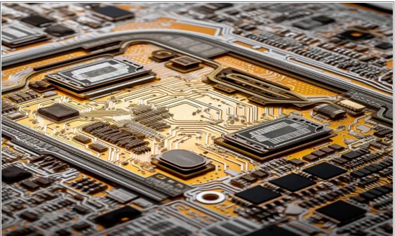
A ceramic PCB uses insulating ceramic materials like alumina or aluminum nitride as the base substrate, often with copper metallization for circuit traces. These boards excel in applications requiring high thermal conductivity and low coefficient of thermal expansion, ideal for hobbyist projects in power electronics or RF modules. Soldering components on ceramic PCBs ensures electrical connectivity while maintaining the board’s thermal performance, but the brittle nature of ceramics demands precise heat control. Improper soldering can cause micro-cracks or delamination, compromising the entire assembly. For hobbyists, mastering ceramic PCB soldering techniques means longer-lasting projects and fewer failures during testing. Adhering to standards like J-STD-001 for soldered assemblies helps guarantee quality from the start.
Ceramic PCBs differ from organic boards in their rigidity and heat resistance, which influences every step of assembly. Components such as resistors, capacitors, or LEDs must bond securely to the metallized pads without stressing the substrate. Soldering matters because it directly affects reliability in demanding environments, like automotive prototypes or high-brightness lighting. Hobbyists often overlook the preparation phase, leading to common issues like poor wetting. By focusing on soldering tips specific to ceramics, you can avoid rework and enjoy smoother builds. This foundation sets the stage for practical application.
Understanding the Technical Principles of Ceramic PCB Soldering
The key challenge in soldering ceramic PCBs stems from the mismatch in thermal expansion between the ceramic substrate, copper traces, and component leads. Ceramics have a very low coefficient of thermal expansion, around one-third that of copper, which can induce stress during heating and cooling cycles. Solder, typically a tin-based alloy, melts at specific temperatures and wets the pads effectively only under controlled conditions. Flux plays a critical role by removing oxides and promoting flow, but aggressive fluxes can damage sensitive ceramic surfaces. Heat transfer on ceramics is rapid due to high thermal conductivity, so localized overheating risks cracking the board. Grasping these principles guides effective soldering techniques for hobbyists.
Another principle involves solder joint formation, where intermetallic compounds develop at the interface for strength. On ceramic PCBs, pads are often thin-film or thick-film metallizations, requiring good solderability as outlined in industry practices. Preheat steps equalize temperatures across the board, minimizing thermal shock. Vapor phase or infrared heating suits ceramics better than convection for uniform profiles, though hobbyists rely on irons. Moisture absorption is less of an issue than with organics, but dry storage prevents any flux-related problems. These mechanisms ensure joints meet performance needs without compromising the substrate.
Essential Tools and Preparation for Soldering Ceramic PCBs
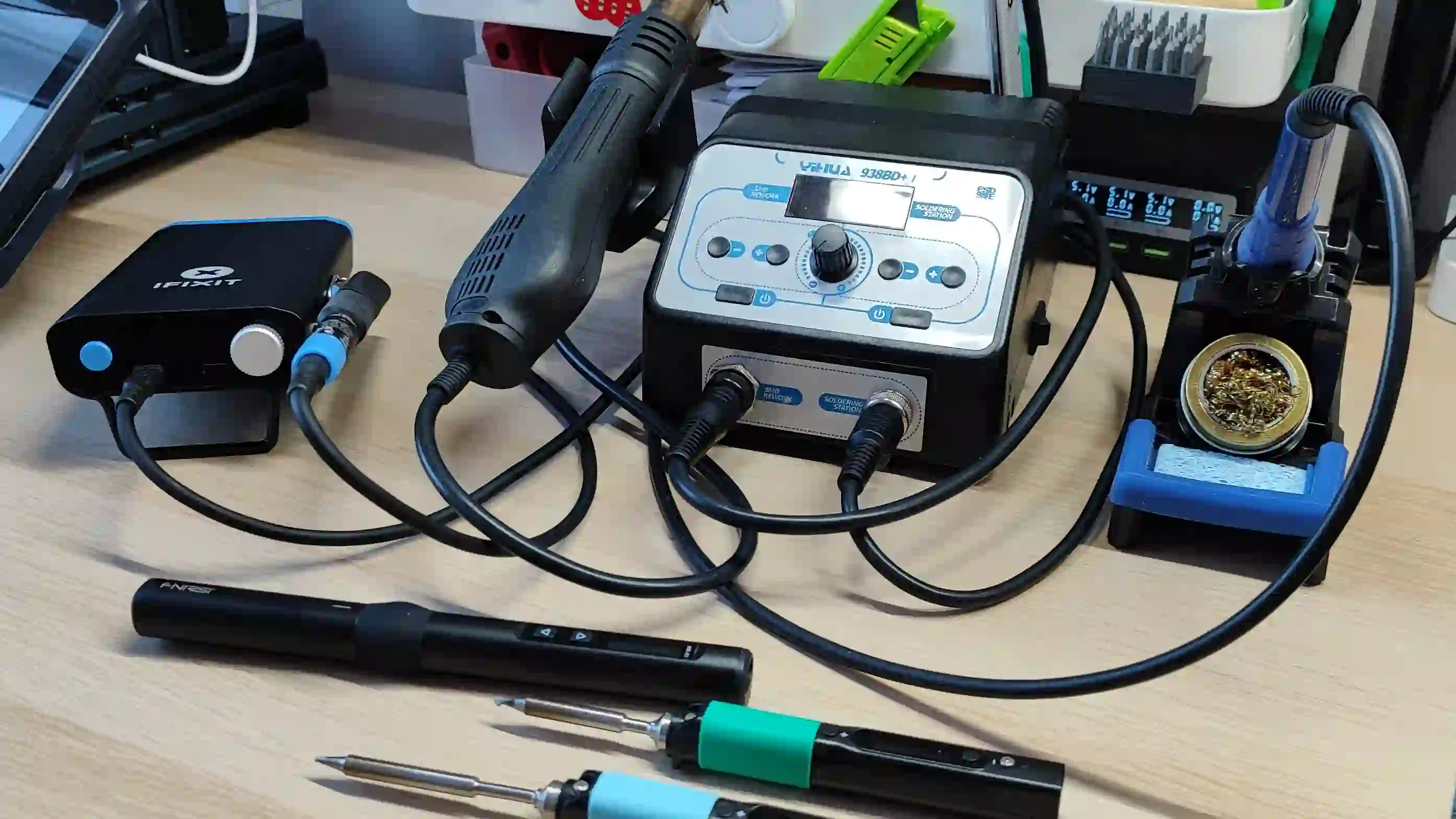
Start with a temperature-controlled soldering iron set to 300-350 degrees Celsius, using fine tips for precision on small pads. A good flux pen enhances wetting, while isopropyl alcohol ensures a clean surface. Tweezers and a magnifying glass aid placement, and a hot air station offers versatility for reflow-like soldering on prototypes. Proper setup prevents common pitfalls, serving as a practical application of the broader principles found in the definitive guide to PCB soldering methodologies.
Preparation involves inspecting the board for defects like warpage or pad lifts before soldering. Apply flux sparingly to pads and component leads to activate surfaces without excess that could trap air bubbles. Pre-tinning pads with a thin solder layer improves initial bonding. Secure the board on a heat-resistant holder to avoid flexing during work. Test your iron’s tip on scrap material to confirm temperature stability. These steps align with best practices for reliable soldering guide outcomes.
Step-by-Step Soldering Techniques for Ceramic PCBs
For through-hole components, insert leads and apply heat to both pad and lead simultaneously, feeding solder until it flows evenly. On ceramic PCBs, this method works well for larger parts like power transistors, but avoid excessive force to prevent board stress. Surface-mount soldering starts with fluxing pads, placing components, and using a fine-tip iron to tack corners before filling joints. Hot air at low flow gently reflows paste for multi-component boards, mimicking professional processes. Always work in a well-ventilated area and use fume extraction for safety. These soldering techniques build confidence for hobbyist ceramic PCB projects.
Hand soldering suits most beginner setups, offering control over heat input critical for ceramics. When evaluating wave soldering vs hand soldering for specialized materials, this manual approach is often preferred for its precision and ability to reduce thermal stress. Begin at one end, progressing systematically to maintain even temperatures, and cool naturally between joints to reduce thermal gradients.
Reflow soldering, accessible via toaster ovens or hot plates for hobbyists, requires a profile with slow ramp-up to avoid shocking the ceramic. Apply solder paste with a spatula or syringe for uniform deposit. Preheat the board 50-100 degrees below melt point to drive off solvents. Position components and reflow, monitoring visually for flow. Clean residues if needed, though no-clean pastes simplify post-process. This technique scales for small batches effectively.
Best Practices and Soldering Tips for Success
Always preheat ceramic PCBs gently with a hot plate or oven to 100-150 degrees Celsius, reducing direct iron shock and CTE stresses. Use lead-free solder for modern compliance, ensuring flux matches alloy type for optimal wetting. Limit dwell time to 3-5 seconds per joint to prevent overheating traces. Angle the iron at 45 degrees for better access on flat ceramic surfaces. Magnify work to spot defects early, aligning with IPC-A-610 visual standards. These soldering tips elevate your ceramic PCB soldering results.
Employ anti-static measures like wrist straps, as ceramics can hold charge affecting sensitive components. Store boards in dry boxes to maintain pad integrity. Rework with desoldering braid carefully, applying flux anew. Document your process for repeatability in future projects. Collaborate with online hobby communities for technique feedback. Consistent application yields professional-grade assemblies.
Troubleshooting Common Issues in Ceramic PCB Soldering
Cracks often arise from rapid heating; solution is consistent preheating and lower iron temps. Poor wetting shows as dewy joints; increase flux or clean better before retrying. Tombstoning in SMDs results from uneven heating; balance heat across parts. Delamination under pads signals contamination; ultrasonic clean or replace board. Overheated components lift off; use clamps for stability. Systematic checks per J-STD-001 resolve most problems efficiently.
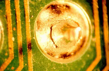
Cold joints appear dull and weak; reheat with flux to reflow. Bridge shorts need wick removal without scraping ceramic. Warped boards from prior processes complicate alignment; flatten under weight pre-assembly. Test continuity post-soldering with a multimeter. Log failures to refine techniques. Troubleshooting sharpens soldering ceramic PCB expertise.
Conclusion
Soldering components on ceramic PCBs rewards hobbyists with robust, high-performance electronics once key principles and techniques are mastered. From preparation and tools to precise application and fixes, each step builds toward flawless joints. Embrace standards like J-STD-001 and IPC-A-610 for guidance, adapting them to your bench setup. Practice iteratively, starting simple, to handle complex layouts confidently. Your projects will thrive with these soldering guide insights, opening doors to advanced thermal-demanding builds. Happy soldering!
FAQs
Q1: What are the main challenges in ceramic PCB soldering for hobbyists?
A1: Ceramic PCB soldering challenges include thermal shock from low CTE materials and rapid heat spread, risking cracks. Use preheating and temp-controlled irons as soldering techniques to mitigate. Flux selection ensures good wetting without residue. Follow J-STD-001 for process controls. These tips make soldering ceramic PCB accessible and reliable.
Q2: What soldering techniques work best for SMD components on ceramic PCBs?
A2: Hand soldering with fine tips or hot air reflow excels for SMD on ceramics, tacking corners first for alignment. Apply no-clean paste or flux for flow. Preheat boards to avoid stress. Inspect per IPC-A-610 criteria. These methods provide durable joints in your soldering guide.
Q3: How can I avoid common mistakes in soldering ceramic PCBs?
A3: Avoid direct high heat; preheat and limit dwell times in your soldering techniques. Clean pads thoroughly for wetting. Use proper flux to prevent oxidation. Check for warpage pre-assembly. These soldering tips ensure strong ceramic PCB soldering outcomes without rework.
Q4: Is hand soldering sufficient for beginner ceramic PCB projects?
A4: Yes, hand soldering suits most hobbyist ceramic PCB projects with temp control and flux. It offers precision for prototypes versus full reflow setups. Practice on scraps builds skill. Adhere to standards for quality. Essential soldering guide for starters.
References
J-STD-001 — Requirements for Soldered Electrical and Electronic Assemblies. IPC, 2020
IPC-A-610H — Acceptability of Electronic Assemblies. IPC, 2019
J-STD-003C — Solderability Tests for Printed Boards. IPC/JEDEC, 2017


