Introduction
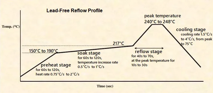
The transition to lead-free solder in PCB assembly has transformed manufacturing practices worldwide, driven primarily by RoHS compliance requirements. Lead-free solders demand elevated reflow temperatures, which place significant thermal stress on PCB substrates, often leading to issues like substrate warpage and delamination. Electrical engineers must select substrates that maintain structural integrity during these high-temperature processes while ensuring reliable performance in the final assembly. This article compares key PCB substrates, highlighting their suitability for lead-free assembly, with a focus on thermal stability, mechanical properties, and practical troubleshooting. By understanding these materials, engineers can optimize designs for high-temperature PCB applications and minimize assembly defects.
The Importance of Substrate Selection in Lead-Free Assembly
RoHS compliance mandates the elimination of lead from solders and materials, shifting the industry to alloys that require higher reflow temperatures than traditional tin-lead options. These elevated process conditions expose substrates to prolonged heat exposure, where materials with insufficient thermal resistance can deform or lose rigidity. Substrate warpage emerges as a critical concern, as uneven thermal expansion disrupts component placement accuracy during SMT and compromises solder joint quality. Engineers prioritize substrates that align with industry standards for thermal performance to achieve RoHS compliance without sacrificing reliability. Selecting the right substrate not only supports lead-free solder processes but also enhances long-term board stability under operational stresses.
In practice, mismatched material properties amplify risks during reflow, where peak temperatures challenge the glass transition temperature of the substrate. Boards processed with inadequate materials often exhibit bowing or twisting, leading to pick-and-place errors and open joints. High-temperature PCB designs demand substrates engineered for dimensional stability, reducing rework and yield losses in assembly lines. Troubleshooting these issues starts with material qualification, ensuring compatibility with lead-free reflow profiles from the outset.
Key Material Properties Influencing Lead-Free Performance
The glass transition temperature marks the point where a substrate shifts from a glassy to a rubbery state, dramatically increasing its coefficient of thermal expansion and risking warpage. Below this threshold, materials retain mechanical strength; above it, expansion mismatches with copper foil can induce stresses that bow the board. Decomposition temperature also plays a role, as substrates must resist breakdown during the soak and reflow phases of lead-free profiles. Electrical engineers evaluate these properties alongside modulus and moisture absorption to predict behavior under thermal cycling. IPC-4101 provides specifications for base materials, guiding selection for rigid and multilayer boards in demanding environments.
Coefficient of thermal expansion alignment between the substrate core and copper layers minimizes warpage during cooling from reflow temperatures. Substrates with lower in-plane CTE values better match copper's expansion characteristics, preventing delamination at vias and pads. Moisture sensitivity exacerbates issues, as absorbed water vaporizes during heating, creating internal pressures akin to popcorn effects. Proper preconditioning per J-STD-020 standards mitigates these risks, ensuring substrates handle lead-free assembly without compromise. Engineers often perform thermal simulations to validate property interactions before committing to production.
High filler content in resins enhances rigidity at elevated temperatures, reducing flex that contributes to warpage. Flame retardancy remains consistent across compliant materials, but thermal class dictates suitability for RoHS processes. Troubleshooting tip: Profile boards with thermocouples during trial runs to identify hot spots where properties falter.
Comparison of Common PCB Substrates for Lead-Free Processes
Standard FR-4 substrates serve general-purpose applications with cost advantages but struggle in lead-free assembly due to limited thermal endurance. These materials soften during prolonged exposure to reflow temperatures, leading to increased warpage and potential interlayer separation. While suitable for low-stress boards, they demand careful process control to avoid defects in high-volume production. Engineers troubleshoot by reinforcing designs with balanced copper distribution, yet limitations persist for denser, multilayer high-temperature PCBs.
High-Tg FR-4 variants address these shortcomings, offering improved heat resistance essential for lead-free solder reflow. They maintain dimensional stability through the entire profile, significantly curbing substrate warpage compared to standard grades. This makes them a go-to for RoHS-compliant assemblies balancing performance and economy. Practical benefits include better via reliability and reduced rework, though thicker boards may still require symmetric layering.
FR-5 phenolic-based substrates provide enhanced mechanical strength and lower moisture absorption, aiding warpage control in lead-free processes. Their higher thermal stability suits applications with multiple reflow passes, where standard FR-4 might fail. Engineers favor them for industrial controls needing robustness, troubleshooting delamination by optimizing lamination cycles. Cost is moderate, positioning FR-5 as a step-up from FR-4 without exotic pricing.
Polyimide substrates excel in extreme high-temperature PCB scenarios, withstanding reflow peaks that defeat epoxy resins. Their flexibility reduces brittleness-induced warpage, ideal for rigid-flex hybrids in lead-free assembly. Drawbacks include higher cost and processing complexity, but reliability in thermal cycling justifies use in aerospace or automotive. Troubleshooting focuses on controlled curing to prevent voids.
BT resin substrates shine in fine-pitch BGA assemblies, boasting low CTE for minimal warpage under lead-free stresses. They pair well with high-density interconnects, ensuring RoHS compliance in compact designs. Engineers mitigate any cupping through core symmetrization and precise drilling.
- Standard FR-4 - Thermal Stability: Moderate; Warpage Resistance: Fair; Cost: Low; Best for Lead-Free: Simple boards
- High-Tg FR-4 - Thermal Stability: Good; Warpage Resistance: Good; Cost: Medium; Best for Lead-Free: General RoHS
- FR-5 - Thermal Stability: Good; Warpage Resistance: Very Good; Cost: Medium; Best for Lead-Free: Multi-reflow
- Polyimide - Thermal Stability: Excellent; Warpage Resistance: Excellent; Cost: High; Best for Lead-Free: Extreme temps
- BT Resin - Thermal Stability: Very Good; Warpage Resistance: Excellent; Cost: High; Best for Lead-Free: High-density
Best Practices for Minimizing Warpage in Lead-Free Assembly
Symmetric stackups counteract asymmetric copper causing bow during reflow, a core troubleshooting strategy for all substrates. Balance inner layer densities to equalize stresses, verifying flatness post-lamination. Fixture boards during assembly to constrain movement, especially for thin high-temperature PCBs.
Bake substrates before processing to remove moisture per J-STD-020 guidelines, preventing vapor-induced warpage. Optimize reflow profiles with gradual ramps, avoiding thermal shocks that amplify CTE differences. Profile diverse board zones to ensure uniform heating.
Material qualification under IPC-6012 ensures performance specs for lead-free viability. Select high-Tg or advanced resins for boards exceeding two reflows. Troubleshoot persistent warpage by analyzing CTE data and adjusting foil types.
Troubleshooting Common Lead-Free Substrate Issues
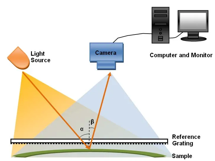
Warpage manifests as bowing post-reflow, often from CTE mismatch; inspect with shadow moiré or dial gauges. Delamination signals overtemperature exposure; cross-section to confirm. Adjust by up-spec'ing to high-Tg materials and refining profiles.
Solderability suffers if substrates degrade; clean residues promptly. For polyimide, watch for resin flow inconsistencies causing voids.
Conclusion
Choosing the optimal PCB substrate for lead-free assembly hinges on balancing thermal properties against application demands, with high-Tg FR-4 emerging as versatile for most RoHS-compliant needs. Advanced options like polyimide and BT resins tackle severe high-temperature PCB challenges, curbing substrate warpage effectively. Engineers armed with standards-guided practices achieve reliable assemblies, minimizing defects and enhancing longevity. Prioritize material testing and process tuning for success in lead-free environments.
FAQs
Q1: What role does glass transition temperature play in selecting substrates for lead-free solder processes?
A1: High-Tg substrates prevent softening during elevated reflow temperatures, reducing substrate warpage and maintaining planarity for accurate component placement. Standard materials may exceed their limits, causing CTE spikes and defects. Engineers specify high-Tg grades per IPC-4101 for RoHS compliance, troubleshooting via thermal profiling. This ensures robust performance in high-temperature PCB assembly.
Q2: How can substrate warpage be minimized during lead-free reflow?
A2: Symmetric copper balancing and fixtures constrain expansion mismatches, key for all substrates. Pre-bake per J-STD-020 removes moisture, averting popcorn effects. Optimize profiles with controlled ramps for uniform heating. High-Tg materials inherently resist deformation better than standard FR-4. Regular warpage checks post-lamination catch issues early.
Q3: Why is RoHS compliance critical for high-temperature PCB substrates?
A3: RoHS eliminates lead, mandating lead-free solder with higher reflow temperatures that stress substrates. Compliant materials like high-Tg FR-4 withstand these without delamination. Non-compliance risks environmental penalties and reliability failures. Select per industry specs for seamless assembly.
Q4: When should polyimide substrates be chosen over FR-4 for lead-free assembly?
A4: Opt for polyimide in extreme reflow or flex applications where FR-4 warps excessively. Its superior thermal stability suits high-temperature PCBs under thermal cycling. Cost trade-offs apply, but reliability gains justify for critical uses. Troubleshoot with precise curing.
References
IPC-4101E — Specification for Base Materials for Rigid and Multilayer Printed Boards. IPC, 2017
J-STD-020E — Moisture/Reflow Sensitivity Classification for Nonhermetic Surface Mount Devices. JEDEC, 2014
IPC-6012DS — Qualification and Performance Specification for Double-Sided Flexible Printed Boards with Rigid Flex Sections. IPC, 2015


