Introduction
Creating a printed circuit board (PCB) is an exciting journey from design to assembly. However, one critical step often overlooked is PCB depaneling, the process of separating individual PCBs from a larger panel after manufacturing. Understanding how to perform manual PCB depaneling effectively ensures the integrity of components and prevents damage like cracked solder joints or broken traces. This tutorial guides engineers through essential methods, including the V-Scoring and Tab-Routing techniques, with a focus on practical, hands-on approaches. Whether prototyping a new project or assembling small batches, mastering manual PCB depaneling will elevate your skills and project outcomes.
The Basics of PCB Depaneling: Why Everyone Should Care
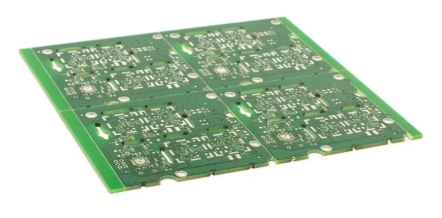
PCB depaneling refers to the process of separating individual circuit boards from a larger panel or array created during manufacturing. Panels streamline production by allowing multiple boards to be fabricated and assembled simultaneously, reducing costs and time.
PCB depaneling is crucial because improper separation can lead to microcracks in the substrate, delamination, or complete board failure. A well-executed process preserves structural and electrical integrity, saves time, and minimizes waste. With limited resources, learning efficient manual PCB depaneling methods like V-Scoring and Tab-Routing ensures cost-effective, reliable results in every project.
PCB Depaneling Methods: Minimizing Mechanical Stress and Substrate Damage
Depaneling methods are designed to minimize mechanical stress based on the panel's layout, board material (e.g., FR-4), and component placement. Stress can cause hidden defects like substrate microcracks or delamination, affecting long-term performance. The two primary techniques are V-Scoring and Tab-Routing.
V-Scoring Technique
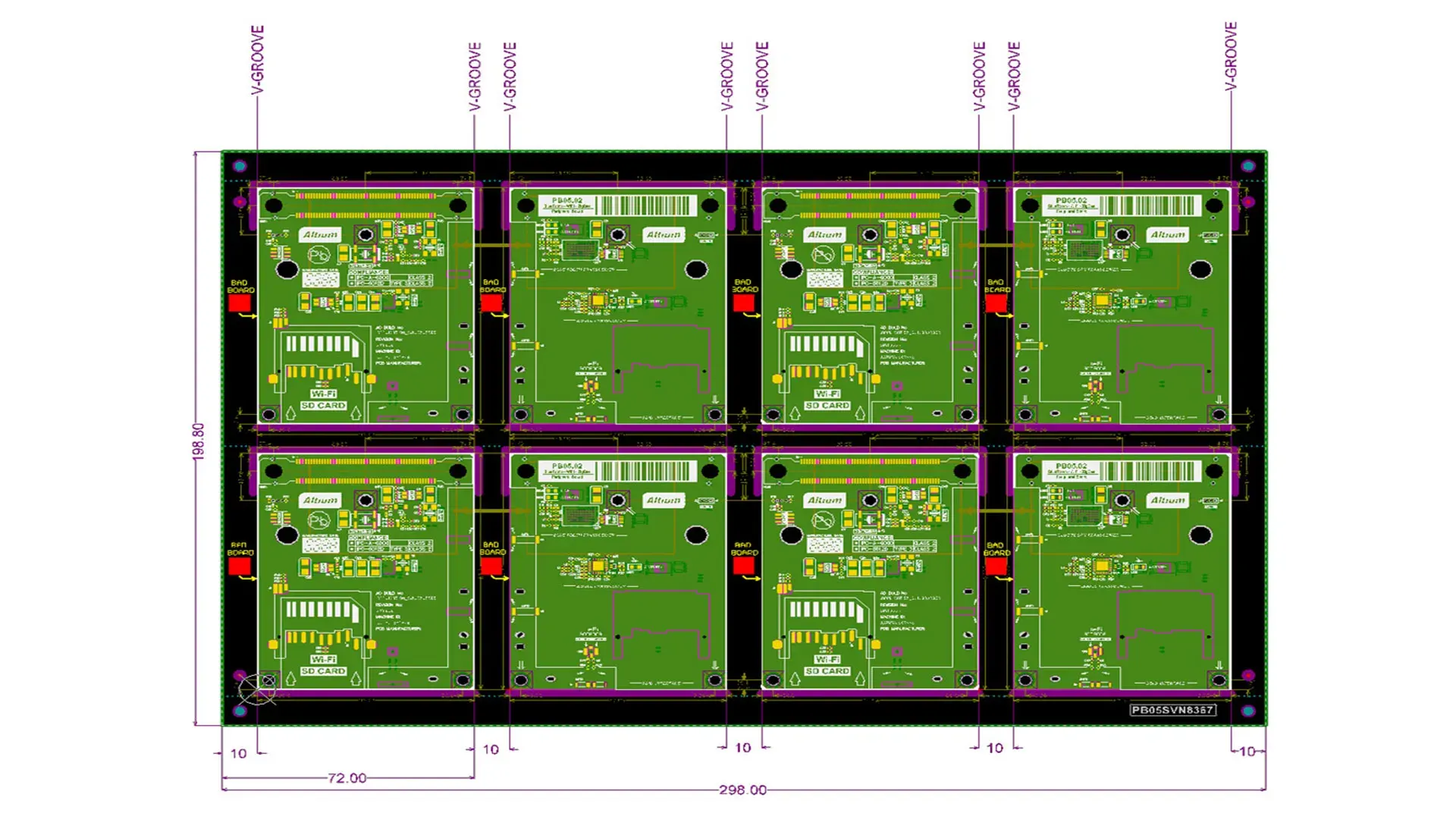
The V-Scoring technique involves creating V-shaped grooves (typically 30–45° angles) along straight separation lines on both sides of the panel, leaving about 1/3 of the board thickness intact. This weakens the material for clean snapping by hand or minimal tools. It works best for rigid boards like FR-4 and straight-line separations. Groove depth is critical—per IPC-6012E, the residual thickness should be controlled (e.g., 0.3–0.4 mm for a 1.6 mm board) to facilitate breaking without compromising handling.
Tab-Routing Technique
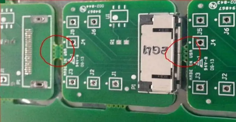
The Tab-Routing technique uses small, breakable tabs (often 2–3 mm wide) to connect boards, frequently perforated with "mouse bites"—drilled holes (e.g., 0.5–0.8 mm diameter, spaced 1 mm apart) for easier separation. A CNC router mills the board outlines, leaving tabs for support. This method suits irregular or curved shapes where V-Scoring is impractical, balancing strength for handling and ease of breaking while managing stress around tabs.
Differences Between V-Scoring and Tab-Routing
V-Scoring and Tab-Routing differ in application, cost, and performance, influencing your choice for PCB depaneling. V-Scoring is ideal for straight, rectangular boards, offering lower costs and faster manual separation but with moderate stress during snapping. Tab-Routing provides flexibility for complex shapes, lower stress with perforated tabs, but higher manufacturing costs due to CNC routing and potential debris cleanup.
| Factor | V-Scoring | Tab-Routing |
|---|---|---|
| Design Flexibility | Limited to straight lines | Supports irregular shapes |
| Cost | Lower, simpler process | Higher due to CNC milling |
| Edge Quality | Potentially rougher edges | Smoother with filing |
| Stress on Board | Moderate during snap | Lower with mouse bites |
| Best For | High-volume rectangular panels | Prototypes, custom designs |
For hobbyists, V-Scoring suits basic projects, while Tab-Routing enables creative layouts.
Suggested Reading: Choosing the Right PCB Depaneling Method: A Comprehensive Comparison
Design Considerations Before PCB Depaneling
Effective PCB depaneling starts in the design phase. Place separation lines (grooves or tabs) at least 3–5 mm away from components to avoid stress-induced damage, per industry guidelines. For V-Scoring, ensure straight edges and no overhanging parts; for Tab-Routing, position 3–5 tabs per side with mouse bites for clean breaks. Use rounded tab corners to reduce stress concentrations. Balance panel layout for even material distribution to prevent warping, and incorporate fiducials or tooling holes for alignment if scaling to automated processes later. Tools like KiCad or Eagle can simulate these for optimal results.
When Is Manual Depaneling the Better Choice
Manual PCB depaneling is preferable for low-volume runs (under 500 panels), prototypes, or simple designs where cost and flexibility matter. It requires no expensive equipment, making it ideal for hobbyists in home workshops. Choose manual over automated when board complexity is low (e.g., no dense components near edges) or for quick iterations, avoiding setup times of routers or lasers. However, for high-reliability needs or large batches, automated methods reduce errors and stress.
Practical Solutions for Manual Depaneling
Manual PCB depaneling is accessible and cost-effective for hobbyists, requiring basic tools and careful technique.
Tools and Safety Precautions
Essential tools include protective gloves, safety glasses, a stable workbench, vise or clamp, pliers (e.g., flush cutters for tabs), a dedicated PCB separator (like pizza cutters for V-scores), fine-grit sandpaper (220–400 grit) for edges, and optionally a Dremel for stubborn stubs. Work in a well-ventilated area to avoid dust inhalation, and always apply controlled force to prevent board flexing. Use ESD-safe tools for populated boards to avoid static damage.
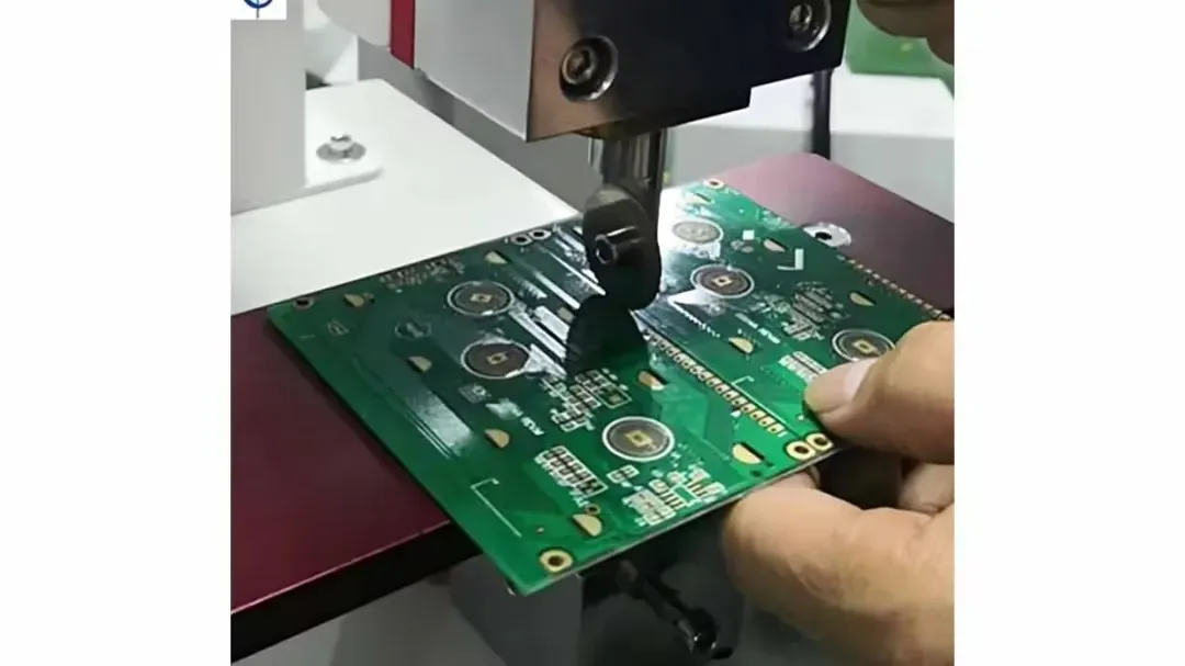
Step-by-Step Guide for V-Scoring Technique
- Inspect the panel for uniform V-grooves (visible shallow lines); measure residual thickness if possible (should be ~1/3 board depth).
- Align the groove over a workbench edge or rigid support (e.g., wooden block) to focus bending force.
- Apply gentle, even pressure with both hands, bending gradually to snap cleanly; for thicker boards (>1.6 mm), use a pizza cutter for precision.
- If resistance occurs, check for misalignment or incomplete scoring; never force to avoid cracks.
- Smooth edges with sandpaper in circular motions, then inspect for burrs under magnification.
This technique minimizes stress for rectangular boards, but practice on scraps first.
Step-by-Step Guide for Tab-Routing Technique
- Identify tabs (often with 3–5 mouse bites); count perforations for weak points.
- Secure the panel in a vise, padding clamps to protect components (keep 5 mm clearance).
- Grip each tab with pliers and twist gently (45° angle) or use a separator tool for leverage; start from corners to distribute stress.
- Proceed systematically around the perimeter, breaking one tab at a time to prevent uneven pulling.
- File stubs with sandpaper or a Dremel (low speed) for a polished, burr-free finish; deburr in a dust-controlled setup.
This method offers versatility for custom shapes, reducing damage with proper tab design.
Related Reading: Depanelization Techniques: Stamp Holes vs. V-Scoring for PCBs
Best Practices for Clean Depaneling
Align separation forces with weak points (grooves or tabs) to minimize propagation of cracks. Avoid excessive bending; use supports under the board for leverage. Shield components near edges with cardboard or foam. Follow IPC-A-600K for post-separation edge inspection, checking for delamination via visual or tap tests. Practice on scrap panels to refine technique, ensuring consistent results.
Troubleshooting Common PCB Depaneling Defects
Uneven breaks in V-scored panels often result from inconsistent groove depth or misalignment—realign and apply uniform pressure. Jagged tab edges from Tab-Routing can snag; file smoothly to resolve. Delamination indicates excessive force or material flaws—reduce pressure and work slowly. Inspect for microcracks using a magnifying glass; if present, salvage by reinforcing with epoxy.
Automated vs Manual Depaneling
Automated PCB depaneling (e.g., routers, lasers) excels in high-volume production with precise, low-stress cuts and repeatability, ideal for complex boards. However, it requires significant investment and setup time. Manual PCB depaneling is better for prototypes, small batches, or hobbyists due to low cost and flexibility, though it risks inconsistencies from human error. For volumes under 500, manual suffices; scale to automated for reliability in larger runs.
Conclusion
Mastering manual PCB depaneling is an essential skill for hobbyists, enabling clean separations using V-Scoring and Tab-Routing without compromising quality. This tutorial outlines design considerations, practical steps, and comparisons to automated methods, emphasizing safety and precision. With practice, these techniques will handle varying complexities, boosting confidence in your projects.
FAQs
Q1: What is the easiest way to learn how to depanel a PCB as a beginner?
A1: For beginners, starting with the V-scoring technique is the easiest approach to learn how to depanel a PCB. It requires minimal tools, often just your hands, and works well for straight-edged boards. Inspect the scored lines, align the panel over a flat edge, and apply gentle pressure to snap it apart. Practice on scrap panels first to build confidence and avoid damaging critical projects.
Q2: How does the V-scoring technique differ from other depaneling methods?
A2: The V-scoring technique uses pre-cut grooves to weaken the panel along straight lines for easy snapping. Unlike tab-routing, which relies on breakable tabs for irregular shapes, V-scoring is simpler and faster for rectangular boards. It also produces less mechanical stress compared to methods like shearing, making it suitable for hobbyists with basic tools and limited experience.
Q3: What tools are recommended for a manual depaneling guide with tab-routing?
A3: For a manual depaneling guide using the tab-routing technique, basic tools include protective gloves, safety glasses, and pliers for breaking tabs. A small vise or clamp helps secure the panel during separation. A fine-grit sandpaper or file is useful for smoothing rough edges after breaking tabs. These tools are affordable and accessible for hobbyists working in a home setup.
Q4: Can the tab-routing technique be used for all PCB shapes?
A4: Yes, the tab-routing technique is versatile and ideal for non-linear or complex PCB shapes where straight cuts like V-scoring are impractical. Tabs with perforations hold the boards in a panel and can be placed strategically to support irregular outlines. This method allows hobbyists to separate custom designs with precision, though care is needed to avoid stress near components.
References
IPC-6012E — Qualification and Performance Specification for Rigid Printed Boards. IPC, 2020.
IPC-A-600K — Acceptability of Printed Boards. IPC, 2020.


