Introduction
Surface mount device (SMD) fuses play a critical role in safeguarding modern electronics, especially on high-density printed circuit boards (PCBs) where space constraints demand compact solutions. These fuses provide essential overcurrent protection by interrupting faulty circuits before damage spreads to sensitive components. As PCB designs evolve toward smaller footprints and higher component density, engineers increasingly rely on SMD fuses for their low profile and compatibility with automated assembly processes. Selecting the right SMD fuse ensures reliability in applications ranging from consumer gadgets to industrial controls. This article explores SMD fuse selection, common sizes like 0603 SMD fuse and 1206 SMD fuse, and best practices for integrating surface mount fuses on PCBs. Understanding these elements helps prevent common pitfalls in dense board layouts.
What Are SMD Fuses and Why Do They Matter in High-Density PCBs?
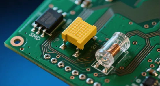
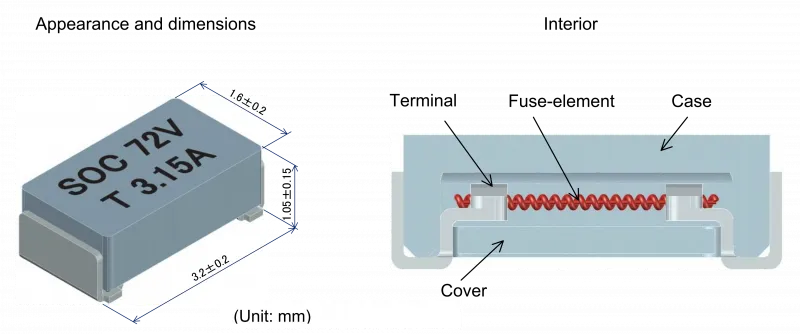
SMD fuses are passive components designed specifically for surface mount technology, featuring a fusible element encased in a ceramic or polymer body with metallized terminals for direct soldering onto PCB pads. Unlike through-hole fuses, they eliminate the need for leads, saving valuable board real estate and enabling tighter component spacing. In high-density PCBs, where trace widths narrow and layer counts rise, SMD fuses matter because they protect power rails and signal lines without compromising layout efficiency. They respond to excessive current by melting the internal element, creating an open circuit that isolates faults. This protection is vital during transient events like power surges or short circuits, which are common in compact designs with closely packed ICs and passives. For electrical engineers, prioritizing SMD fuses aligns with the push for miniaturization while maintaining system integrity.
The relevance grows with the shift to finer-pitch components and multilayer boards, where traditional protection methods simply do not fit. SMD fuses support reflow soldering, integrating seamlessly into surface mount assembly lines. Their compact nature reduces parasitic inductance, improving response times in high-frequency circuits. Engineers must consider them early in the design phase to avoid rework during prototyping.
Technical Principles of SMD Fuses
SMD fuses operate on the principle of thermal overload, where current passing through a low-melting-point alloy or wire generates heat proportional to I squared R losses. When current exceeds the rated value, the element reaches its melting point, breaking the circuit and halting flow. Key characteristics include rated current, voltage, interrupting rating, and time-current curve, which defines blow time under various overloads. Fast-acting fuses blow quickly for sensitive electronics, while slow-blow versions tolerate inrush currents from capacitors or motors. Material choices, such as ceramic housings, enhance thermal stability and arc quenching in higher voltage applications.
Size designations follow imperial metrics, with 0603 SMD fuse measuring approximately 1.6 mm by 0.8 mm and 1206 SMD fuse at 3.2 mm by 1.6 mm. These dimensions dictate power dissipation and current handling, with smaller sizes suiting low-power circuits and larger ones for higher loads. Land pattern design for these components adheres to IPC-7351 guidelines to ensure optimal solder joint formation and mechanical strength. Voltage ratings typically range from 32 V to 63 V DC, matching common PCB power domains.
Response characteristics vary by construction; thin-film elements provide precise blowing, while thicker wires offer robustness. Engineers evaluate I2t values to match fuse performance with circuit energy withstand during faults. Environmental factors like temperature derating affect selection, as higher ambient heat reduces holding current.
SMD Fuse Sizes: Matching Dimensions to PCB Constraints
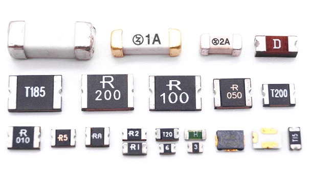
SMD fuse sizes standardize around package codes like 0402, 0603, 0805, 1206, and larger variants up to 2410, each balancing protection needs with board space. The 0603 SMD fuse excels in ultra-dense layouts, fitting between fine-pitch ICs and passives where every millimeter counts. Its small footprint minimizes shadow effects during reflow, promoting uniform heating. However, limited surface area caps its power handling, making it ideal for signal-level or low-current protection.
In contrast, the 1206 SMD fuse offers greater robustness for moderate power rails, with wider terminals that enhance solder fillet formation and heat dissipation. This size suits applications needing higher interrupting capacity without jumping to bulky alternatives. Surface mount fuse PCB integration requires precise pad sizing; undersized pads lead to tombstoning, while oversized ones cause bridging. Standard metric equivalents, such as 1608 for 0603, aid global sourcing consistency.
Larger sizes like 1206 provide better thermal margins in multilayer stacks with buried power planes. Engineers plot size against expected load using derating curves from datasheets. Visual inspection post-assembly confirms joint quality per IPC-A-610 criteria.
SMD Fuse Selection: Key Criteria for Electric Engineers
Effective SMD fuse selection starts with defining circuit parameters: maximum steady-state current, expected transients, voltage, and fault energy. Choose a fuse rated 25 to 50 percent above normal operating current to account for temperature rise and aging, ensuring it holds under full load. Voltage rating must exceed the system's absolute maximum, including transients. Interrupting rating should surpass potential short-circuit currents, often calculated from supply impedance.
Time-current characteristics guide type choice; fast-acting for digital circuits prone to latch-up, slow-blow for inductive loads with startup surges. Consider melting I2t to coordinate with downstream components. Package size follows from power needs: opt for 0603 SMD fuse in space-critical areas, scaling to 1206 SMD fuse for reliability emphasis. Moisture sensitivity level (MSL) per IPC/JEDEC J-STD-020 dictates handling and storage to prevent reflow defects.
Environmental quals like thermal shock and humidity testing ensure longevity. Voltage coefficient and pulse withstand verify suitability for switching noise. Prototype testing validates selection through accelerated life cycles.
Best Practices for Surface Mount Fuse PCB Implementation
Position SMD fuses close to protected components or entry points to minimize unprotected trace lengths, reducing fire risk from arcs. Orient them parallel to airflow for cooling, avoiding hotspots near high-power ICs. Pad layouts per IPC-7351 prevent solder defects; use solder mask defined pads for finer pitches.
Reflow profiles must align with component MSL, baking if needed before exposure. Solder paste volume control via stencil apertures avoids excess that causes floating. Post-reflow X-ray or AOI checks joint integrity against IPC-A-610 Class 2 or 3 criteria, depending on application.
Routing keeps fuse traces wide enough for current without necking, using vias for heat sinking if multilayer. Ground planes under fuses aid dissipation but require thermal reliefs.
Troubleshooting Common SMD Fuse Issues on PCBs
Open fuses often trace to underrated selection or transients; measure inrush with scope to confirm. False blows from vibration suggest mechanical weakness, fixed by adhesive dots or underfill. Solder defects like head-in-pillow manifest as high resistance; rework with hot air, verifying alloy compatibility.
Tombstoning in 0603 SMD fuses stems from uneven paste or reflow ramps; adjust stencil thickness and profile soak time. Overheating without blowing indicates parallel paths bypassing protection; audit layout for sneak currents. Failed interrupts from arcs require higher-rated fuses or snubbers.
Aging shows as drift in holding current; cycle testing reveals marginal designs. Replace with exact matches, desoldering carefully to avoid board damage.
Conclusion
SMD fuses deliver essential compact protection for high-density PCBs, with sizes like 0603 and 1206 enabling dense layouts without sacrifice. Proper SMD fuse selection hinges on current, voltage, and response matching to circuit demands, guided by standards like IPC-7351 and J-STD-020. Best practices in placement, soldering, and troubleshooting ensure long-term reliability. Electrical engineers benefit from early integration and validation, avoiding costly field failures. As boards shrink further, these components remain a cornerstone of robust design.
FAQs
Q1: How do I perform SMD fuse selection for a high-density surface mount fuse PCB?
A1: Start by calculating maximum load current with a 25-50% margin, then match voltage and interrupting ratings. Review time-current curves for transient tolerance, selecting fast or slow-blow as needed. Factor in PCB temperature rise and size constraints, using 0603 SMD fuse for tight spaces or 1206 SMD fuse for higher power. Validate with simulations and prototypes to confirm coordination. This practical approach prevents nuisance trips and underprotection.
Q2: What are standard SMD fuse sizes and their applications on PCBs?
A2: Common SMD fuse sizes include 0603 (1.6x0.8 mm) for low-power signals and 1206 (3.2x1.6 mm) for moderate rails in dense boards. Smaller sizes suit wearables and IoT, while larger handle automotive loads. Choose based on dissipation needs and land patterns per IPC standards. They integrate via reflow, supporting automated assembly without leads.
Q3: Why choose a 0603 SMD fuse over larger options for PCB protection?
A3: The 0603 SMD fuse fits ultra-compact layouts, minimizing footprint amid fine-pitch components. It offers quick response for sensitive circuits, with low inductance aiding high-speed signals. It is ideal where space trumps power, but apply thermal derating. Reliable assembly requires precise stencil design and reflow control to avoid defects like tombstoning.
Q4: What best practices ensure reliable 1206 SMD fuse performance?
A4: Place fuses near loads with wide traces and thermal vias for cooling. Use J-STD-001 compliant soldering profiles, inspecting joints per IPC-A-610. Validate pulse withstand, interrupting rating, and aging with representative prototypes. Maintain proper pad sizing per IPC-7351 and control solder paste volume to prevent solder defects.
References
IPC-7351C - Generic Requirements for Surface Mount Design and Land Pattern Standard. IPC, 2018
IPC/JEDEC J-STD-020E - Moisture/Reflow Sensitivity Classification of Nonhermetic Surface Mount Devices. JEDEC, 2014
IPC-A-610H - Acceptability of Electronic Assemblies. IPC, 2019
J-STD-001H - Requirements for Soldered Electrical and Electronic Assemblies. IPC, 2018


