Introduction
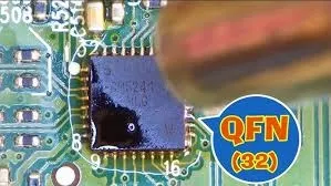
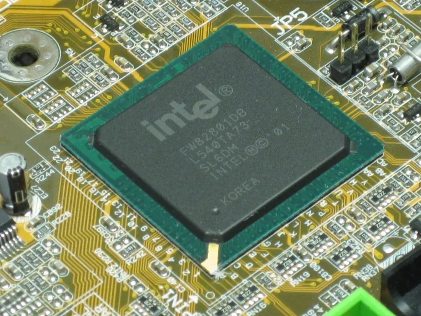
Modern PCBs contain 0402 resistors, 0.4 mm pitch QFN/BGA packages, and multilayer PCB that demands precise thermal control during rework. A proper hot-air rework station with closed-loop temperature and adjustable airflow makes SMD component removal and replacement safe and repeatable. This field-proven SMT rework tutorial covers every step used daily on high-reliability production lines.
Essential Rework Tools
- Hot-air station with accurate temperature (±2 °C) and airflow control
- Bottom IR or convection preheater (essential for boards > 1.0 mm thick)
- No-clean tacky flux (gel or paste)
- Low-melting-point or standard 63/37 or SAC305 solder wire
- ESD-safe tweezers and vacuum pick-up
- 10–45× stereo microscope
- 99 % IPA and cleaning swabs
Step-by-Step Removal Process
Step 1: Preparation
- Bake board 4 h @ 105 °C if stored > 3 months (removes moisture)
- Identify component orientation and pin-1 marking
- Apply generous tacky flux around the component
Step 2: Preheating
- Set bottom preheater to 120–150 °C
- Wait until board reaches 100–120 °C (use IR thermometer)
- This prevents thermal shock and reduces top temperature needed
Step 3: Hot-Air Removal
Typical settings for lead-free SAC305:
| Package | Nozzle Size | Top Temp | Airflow | Distance | Time to Lift |
|---|---|---|---|---|---|
| 0402–1206 | 3–5 mm | 330–350 °C | Low 10–20 | 5–8 mm | 20–40 s |
| SOIC/QFP | 8–15 mm | 340–370 °C | Medium 30–40 | 6–10 mm | 40–70 s |
| QFN/BGA | Component size + 2 mm | 350–380 °C | Low 15–25 | 5–8 mm | 60–120 s |
Technique:
- Move nozzle in small circles or figure-8 pattern
- Watch for uniform gloss across all joints (indicates liquidus)
- Lift component straight up with vacuum tool when solder is fully molten
- Never twist or apply side force
Step 4: Site Cleaning
- Remove excess solder with wick + flux while pads are hot
- Clean residual flux with IPA and swab
- Verify all pads are flat and undamaged under microscope
Step-by-Step Replacement Process
Step 1: Pad Preparation
- Apply thin layer of tacky flux to all pads
- Pre-tin pads very lightly with solder wire if needed (especially after removing large QFN thermal pad)
Step 2: Component Alignment
- Place new component using vacuum pick-up or tweezers
- Align perfectly under microscope before heating
Step 3: Reflow
- Use same preheat and top temperature settings as removal
- Apply gel flux around perimeter if needed
- Heat until all joints show uniform wetting and slight fillet formation
- Keep airflow low to prevent component movement
Step 4: Inspection and Cleaning
- Inspect every joint at 20–40× magnification
- Clean flux residue only if required (no-clean flux can stay)
- Verify no bridges, cold joints, or tombstoning
Advanced Tips for Difficult Packages
QFN / LGA with Large Thermal Pad
- Apply extra flux under component before placement
- Use bottom preheater at 150–180 °C for boards > 1.6 mm
- Slightly longer dwell time (15–20 s after liquidus) ensures center pad wetting
0.4 mm Pitch BGA
- Use correct SMT stencil for reballing or pre-balled device
- Set top temperature 20 °C lower than removal
- Watch for self-centering during reflow
0402 / 0201 Passives
- Lowest possible airflow (10–15 L/min)
- 3 mm nozzle or focused nozzle tip
- 300–320 °C top temperature
Common Rework Defects and Fixes
| Defect | Cause | Fix |
|---|---|---|
| Component shift | High airflow | Reduce airflow, use larger nozzle |
| Pad lift | Excessive temperature/time | Lower top temp 10–20 °C, increase preheat |
| Bridging | Too much solder | Clean pads thoroughly before replacement |
| Tombstoning | Uneven heating | Ensure uniform preheat, perfect alignment |
| Non-wetting | Oxidized pads | Fresh flux + light pre-tinning |
Conclusion
Successful SMD rework depends 80 % on proper thermal profile and 20 % on mechanical skill. Always preheat from bottom, use fresh no-clean flux, keep airflow low, and watch for uniform reflow gloss. With practice on scrap boards, even beginners achieve first-pass yields above 98 % on 0402 to 0.4 mm pitch packages.
FAQs
QX: Do I need a bottom preheater for thin boards?
AX: Not mandatory below 1.0 mm, but strongly recommended above 1.2 mm or with large ground planes.
QX: What temperature is safe for most modern components?
AX: Peak component body temperature ≤ 260 °C for 30–40 s is safe for nearly all RoHS parts.
QX: Can I reuse removed components?
AX: Only passives and simple ICs if pads are intact and no overheating occurred. Never reuse BGAs.
QX: How do I know when solder is fully molten?
AX: All joints turn uniformly shiny and the component self-aligns or moves easily when nudged.
References
IPC-7711/7721C — Rework, Modification and Repair of Electronic Assemblies. IPC, 2017.
IPC J-STD-001H — Requirements for Soldered Electrical and Electronic Assemblies. IPC, 2020.
IPC-A-610H — Acceptability of Electronic Assemblies. IPC, 2020.
JEDEC J-STD-020E — Moisture/Reflow Sensitivity Classification for Nonhermetic Surface Mount Devices. JEDEC, 2014.


