Introduction
Flex PCBs offer unique advantages in applications requiring compact, lightweight, and dynamically bending electronics, such as wearables, medical devices, and automotive sensors. However, flex PCB assembly problems arise primarily from the substrate's inherent flexibility, which complicates standard surface-mount technology processes. During installation preparation, issues like warpage, misalignment, and solder joint failures can lead to unreliable final assemblies. Engineers must address these flex PCB assembly defects systematically to ensure performance under mechanical stress. This article explores common challenges in solder paste printing on flex PCBs, component placement on flexible PCBs, reflow soldering flex PCBs, and related defects. By understanding root causes and applying targeted solutions, assembly yields improve significantly.
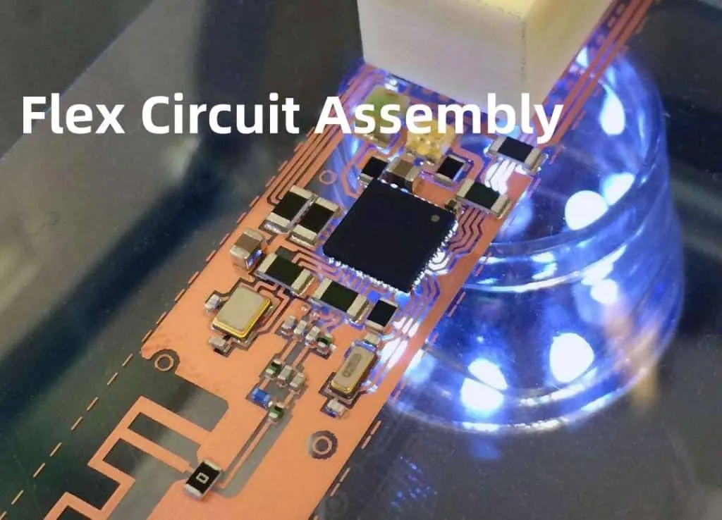
Flex-to-install assembly refers to the process of populating flexible circuits for integration into end products, often involving rigid-flex hybrids. The flexibility that enables design innovation also introduces variability in handling and thermal exposure. Poor management results in defects that compromise electrical integrity and mechanical durability. Practical troubleshooting focuses on fixturing, process controls, and material compatibility to mitigate these risks.
Key Stages in Flex PCB Assembly and Why They Matter
Flexible PCB assembly follows standard SMT steps: solder paste application, component placement, reflow soldering, and inspection, but adaptations are essential due to material behavior. Solder paste printing demands precise stencil-to-substrate registration, as flexing disrupts uniform deposition. Component placement requires stabilization to prevent shifts from board movement. Reflow soldering must account for uneven heating that exacerbates warpage. Inspection verifies joint quality against criteria like those in IPC-A-610 for electronic assemblies.
These stages matter because flex substrates, typically polyimide-based, exhibit higher coefficients of thermal expansion than rigid FR-4, leading to stress concentrations. Unaddressed flex PCB assembly problems result in field failures, such as intermittent opens from cracked joints during product flexing. Proactive measures align with industry standards to achieve reliable installations. Engineers benefit from structured diagnostics to isolate issues early.
Solder Paste Printing Challenges on Flex PCBs
Solder paste printing on flex PCBs often suffers from misalignment and uneven deposition due to substrate deflection under stencil pressure. Without proper support, the flex material bows, causing apertures to misregister with pads and resulting in insufficient or excess paste. This leads to downstream defects like open joints or bridges during reflow. Ambient conditions, such as humidity, further degrade paste release from the stencil.
To troubleshoot, implement vacuum hold-down pallets or contour pins that conform to the flex contour, minimizing lift-off. Automated vision alignment systems ensure sub-pad tolerance registration. Select type 4 or finer paste particles for better flow on uneven surfaces, and optimize squeegee pressure for clean release. Post-print solder paste inspection confirms volume uniformity across the panel.
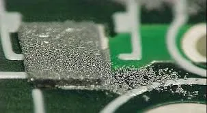
Regular stencil cleaning prevents residue buildup, which worsens on flex due to prolonged contact times. Process controls like controlled print speed and snap-off distance enhance consistency. These practices reduce flex PCB assembly defects originating from printing by over half in typical runs.
Suggested Reading: Solder Paste Printing for Flexible PCBs: Challenges and Solutions
Component Placement Issues on Flexible PCBs
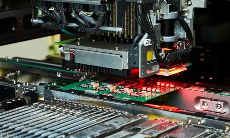
Component placement on flexible PCBs faces challenges from board warpage and movement during pick-and-place operations. The lack of rigidity causes fiducials to shift, leading to offsets that propagate to reflow tombstoning. Fine-pitch devices amplify errors, as even minor flexing displaces components. Manual handling exacerbates this through unintended bending.
Solutions center on rigid carriers or perforated pallets that secure the flex flat without adhesive residue. High-resolution vision systems with flex-specific algorithms compensate for real-time deformation. Place heavier components on stiffened areas to distribute load evenly. Pre-bake panels to remove moisture, preventing popcorning that warps the board further.
Post-placement verification via automated optical inspection catches misalignments before reflow. Adjusting nozzle vacuum and speed for delicate flex handling prevents pad damage. These steps ensure accurate positioning, critical for high-density flex-to-install assemblies.
Reflow Soldering Problems with Flex PCBs
Reflow soldering flex PCBs introduces defects like solder bridges, cold joints, and lifted pads from thermal gradients across the thin substrate. Flex materials absorb heat unevenly, causing curl that pulls components off pads. Moisture entrapment leads to delamination or voids, compromising joint integrity. Excessive peak temperatures exacerbate copper migration or trace cracking.
Develop custom reflow profiles with extended preheats for uniform ramp-up, followed by controlled cooling to minimize stress. Use nitrogen atmospheres to reduce oxidation on pads. Carrier fixtures maintain planarity through the oven, preventing warpage per IPC-6013 qualification for flexible boards. Flux selection with high activity aids wetting on flexible surfaces.
Lifted pads often stem from mechanical stress during flexing in the oven; reinforce with underfill post-reflow for critical joints. Thermal profiling tools map hotspots specific to flex stackups. These interventions align joints with acceptability criteria, enhancing reliability.
Other Common Flex PCB Assembly Defects
Beyond core processes, defects like pad cratering and solder joint cracking occur from repeated handling stresses. Coverlay offsets expose traces, inviting shorts, while unsupported pads lift under thermal expansion mismatch. Conformal coating failures, such as cracking on bends, arise from rigid materials incompatible with flexing.
Troubleshoot by adding polyimide stiffeners under component areas for mechanical support. Conduct bend tests post-assembly to validate durability. For coating, apply flexible silicone types with uniform thickness via selective spraying. Rework demands low-heat tools to avoid substrate damage.
IPC-A-610 guidelines help classify these defects, guiding acceptance decisions. Root cause analysis via cross-sectioning reveals layer adhesion issues.
Best Practices for Reliable Flex-to-Install Assembly
Integrate fixtures throughout the line to standardize handling. Bake flex panels before printing to control moisture per standard handling protocols. Employ SPI and AOI at each stage for early detection. Design panels with multiple fiducials and tear-away tabs for stability. Collaborate on stackup reviews to optimize coverlay and stiffener placement. Simulate reflow profiles virtually to predict warpage. Document process deviations for continuous improvement. These practices minimize flex PCB assembly defects, ensuring robust installations.
Conclusion
Troubleshooting flex-to-install PCB assembly requires addressing flex PCB assembly problems at their source: printing inconsistencies, placement instability, reflow stresses, and handling defects. Fixtures, process tuning, and standards compliance form the backbone of solutions. Engineers achieve higher yields by prioritizing support mechanisms and verification. Implementing these strategies leads to durable, high-performance flex assemblies ready for demanding applications.
FAQs
Q1: What are the most common flex PCB assembly problems?
A1: Flex PCB assembly problems frequently include solder paste misalignment, component shifts during placement, reflow-induced warpage, and lifted pads. These stem from substrate flexibility causing uneven support and thermal response. Use vacuum fixtures and vision-guided processes to stabilize the board. Standards like IPC-A-610 aid in defect classification for systematic fixes.
Q2: How can I improve solder paste printing on flex PCBs?
A2: Improve solder paste printing by using contour-matching pallets to prevent bowing and automated alignment for precise registration. Optimize paste rheology and stencil design for clean release. Post-print inspection verifies uniformity. Environmental controls reduce humidity effects. These steps effectively cut printing-related flex PCB assembly defects.
Q3: What challenges occur in component placement on flexible PCBs?
A3: Placement challenges include warpage and movement that cause offsets and tombstoning risks. Secure panels on rigid carriers with vacuum hold-down, and use advanced vision systems to track fiducials dynamically. Place components on stiffened zones and adjust handling parameters to ensure accurate placement before reflow.
Q4: How to prevent defects during reflow soldering flex PCBs?
A4: Prevent defects by creating custom thermal profiles with gradual heating and using fixtured carriers to control curl. Nitrogen purging minimizes oxidation, and pre-baking avoids moisture-related voids. Consider underfill for stressed joints and verify performance against IPC-6013 to ensure robust solder joints.
References
IPC-A-610 — Acceptability of Electronic Assemblies. IPC
IPC-6013 — Qualification and Performance Specification for Flexible Printed Boards. IPC
IPC-2223 — Sectional Design Standard for Flexible/Rigid-Flexible Printed Boards. IPC


