Introduction
In high-frequency PCB designs, signal integrity remains a critical concern for electrical engineers. As operating frequencies push into the GHz range, factors like signal loss, reflections, and impedance mismatches can degrade performance and lead to system failures. The choice of PCB material directly influences these parameters through its dielectric properties. CEM-3 emerges as a compelling option among high-frequency PCB materials due to its balanced electrical and mechanical characteristics. This article explores how CEM-3 dielectric properties contribute to superior signal integrity CEM-3 implementations, particularly in impedance control CEM-3 applications. Engineers can leverage these traits to optimize designs without compromising reliability.
What Is CEM-3 and Why It Matters for High-Frequency Designs
CEM-3 is a composite epoxy material classified under established laminate specifications, featuring a core of non-woven glass mat sandwiched between woven glass cloth layers impregnated with epoxy resin. This construction provides enhanced uniformity compared to traditional woven-glass-only laminates, making it suitable for double-sided and select multilayer boards. In high-frequency applications, where signal propagation speed and minimal attenuation are paramount, CEM-3 stands out for its stable electrical performance. Its dielectric properties ensure consistent signal transmission, reducing variations that plague less uniform materials. For electrical engineers tackling high-frequency PCB materials selection, CEM-3 offers a practical balance of cost and performance, excelling in environments demanding precise control over electromagnetic behavior. As designs evolve toward faster data rates, understanding CEM-3's role becomes essential for maintaining signal fidelity.
Key Dielectric Properties of CEM-3 and Their Impact on Signal Integrity
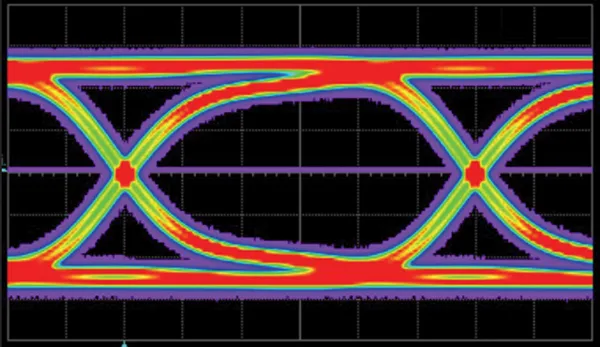
The dielectric constant of CEM-3 remains stable across a range of frequencies, facilitating predictable signal propagation in high-speed circuits. This stability minimizes timing skew and supports accurate impedance control CEM-3 strategies. Coupled with a low dissipation factor, CEM-3 exhibits reduced CEM-3 PCB signal loss, allowing signals to travel longer distances with less attenuation. In contrast to materials with higher loss tangents, CEM-3 preserves waveform integrity, crucial for eye diagram quality in serial links. Electrical engineers appreciate how these properties align with IPC-6012 performance specifications for rigid printed boards. Overall, CEM-3 dielectric properties enable robust high-frequency operation without the need for exotic substrates.
Signal loss in PCBs arises primarily from dielectric absorption and conductor effects, both mitigated effectively by CEM-3. The non-woven glass mat contributes to isotropic dielectric behavior, reducing anisotropy-related distortions common in woven reinforcements. This uniformity aids in maintaining characteristic impedance, essential for matching transmission lines to drivers and receivers. Engineers can achieve tighter impedance tolerances, often within 10 percent, through careful stackup design using CEM-3. Furthermore, the material's low moisture absorption prevents dielectric constant shifts post-fabrication, ensuring long-term signal integrity CEM-3 reliability. These attributes position CEM-3 as a go-to for applications like RF modules and high-speed digital interfaces.
Mechanisms Behind CEM-3's Superior Performance in High-Frequency Environments
At high frequencies, electromagnetic waves interact strongly with the PCB substrate, where dielectric losses convert signal energy to heat. CEM-3's optimized resin-glass matrix minimizes this dissipation, outperforming composite materials with coarser reinforcements. The epoxy formulation provides excellent adhesion to copper, reducing interfacial losses at conductor-dielectric boundaries. This leads to lower insertion loss per unit length, vital for multi-gigabit-per-second links. Impedance control CEM-3 benefits from the material's consistent thickness control during lamination, avoiding variations that cause return loss. Compliance with IPC-A-600 acceptability criteria further validates CEM-3's suitability for production-scale high-frequency boards.
Skin effect and dielectric polarization dominate losses beyond 1 GHz, yet CEM-3 handles these gracefully due to its smooth surface finish and low roughness. The non-woven core distributes stresses evenly, preventing microcracks that could introduce parasitic capacitance. In differential signaling, this translates to balanced skew and common-mode rejection. Engineers modeling with field solvers note CEM-3's predictability, simplifying pre-layout simulations. Thermal stability during operation prevents Dk drift, maintaining signal integrity under load. Thus, CEM-3 excels where high-frequency PCB materials must deliver both electrical precision and mechanical robustness.
Practical Best Practices for Implementing CEM-3 in High-Frequency Designs
Selecting CEM-3 begins with verifying compatibility with target frequencies, typically up to several GHz for most applications. Design stackups with symmetric builds to control warpage, using standard core and prepreg combinations. For impedance control CEM-3, employ microstrip or stripline geometries with controlled trace widths and spacing, validated via TDR measurements. Minimize vias by routing critical nets on inner layers, reducing discontinuities that exacerbate CEM-3 PCB signal loss. Fabricate with tight copper weight tolerances to preserve skin effect performance. Adhering to J-STD-001 requirements during assembly ensures solder joints do not compromise high-frequency paths.
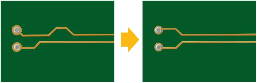
Routing guidelines emphasize length matching for differential pairs, leveraging CEM-3's low skew potential. Avoid right-angle bends, opting for mitered corners to curb reflections. Ground planes should be poured solidly beneath high-speed traces for return path integrity. During prototyping, characterize boards with VNA sweeps to quantify S-parameters, confirming low CEM-3 PCB signal loss. Post-layout reviews should include crosstalk simulations, where CEM-3's properties shine. These practices enable electrical engineers to harness CEM-3 dielectric properties fully, achieving production-ready high-frequency designs.
Troubleshooting Common Signal Integrity Issues with CEM-3
Occasional impedance deviations in CEM-3 boards often stem from plating variations in through-holes, addressable by specifying uniform barrel profiles. If signal attenuation exceeds expectations, inspect for resin voids via cross-sectioning, ensuring lamination follows IPC guidelines. Crosstalk spikes may indicate inadequate plane partitioning; stitch vias densely along boundaries. For resonance issues, add decoupling capacitors tuned to the frequency band. Moisture ingress can subtly elevate losses, so bake boards pre-assembly per JEDEC standards. Systematic debugging with time-domain reflectometry isolates faults efficiently in CEM-3 high-frequency setups.
Conclusion
CEM-3 PCBs provide a reliable foundation for boosting signal integrity in high-frequency designs through their stable dielectric properties and low loss characteristics. Electrical engineers benefit from consistent impedance control and minimal CEM-3 PCB signal loss, making it ideal for cost-sensitive yet performance-demanding projects. By understanding its mechanisms and applying best practices, designs achieve superior eye heights and bit error rates. As high-frequency PCB materials evolve, CEM-3 remains a versatile choice aligned with industry standards. Integrating these insights ensures robust, future-proof electronics.
FAQs
Q1: What makes CEM-3 dielectric properties advantageous for signal integrity CEM-3?
A1: CEM-3 features a stable dielectric constant and low dissipation factor, which minimize signal attenuation and support precise impedance matching. The non-woven glass core ensures uniformity, reducing variations in propagation delay across the board. This combination excels in high-frequency environments up to GHz ranges, maintaining waveform integrity without exotic materials. Engineers rely on these traits for reliable digital and RF performance.
Q2: How does CEM-3 compare to other high-frequency PCB materials in terms of signal loss?
A2: CEM-3 offers competitive CEM-3 PCB signal loss due to its optimized epoxy-glass composition, suitable for medium-to-high-speed applications. While specialized laminates provide marginally lower Df, CEM-3 balances cost with performance for most designs. Its stability prevents frequency-dependent degradation, making it preferable for production volumes. Logical selection involves matching loss budgets to system requirements.
Q3: What best practices ensure effective impedance control CEM-3?
A3: Design symmetric stackups and use field solvers for trace geometries tailored to CEM-3 properties. Maintain consistent dielectric thickness through controlled pressing. Route high-speed nets over solid planes and verify with TDR post-fabrication. These steps achieve tolerances essential for high-frequency signal integrity.
Q4: Can CEM-3 handle multilayer high-frequency designs?
A4: Yes, CEM-3 supports select multilayer configurations with proper prepreg integration, leveraging its mechanical stability. Focus on low layer counts for optimal CEM-3 dielectric properties uniformity. Adhere to standards for via reliability to preserve signal paths.
References
IPC-6012E — Qualification and Performance Specification for Rigid Printed Boards. IPC, 2017
IPC-A-600K — Acceptability of Printed Boards. IPC, 2020
J-STD-001H — Requirements for Soldered Electrical and Electronic Assemblies. IPC, 2020