Introduction
High-frequency applications, such as telecommunications, radar systems, and high-speed data processing, place stringent demands on printed circuit board performance. Epoxy resin PCBs have long served as a foundational material due to their mechanical strength and process compatibility, but traditional formulations struggle with signal attenuation at frequencies above 1 GHz. Advances in low loss epoxy resin formulations address these challenges by offering improved electrical properties tailored for high frequency epoxy resin PCB designs. Engineers must prioritize material selection and design strategies to maintain signal integrity epoxy resin performance while controlling costs. This article explores the critical properties of dielectric constant epoxy resin materials, impedance control epoxy resin techniques, and best practices for reliable operation. By understanding these elements, designers can optimize boards for minimal loss and maximum efficiency in demanding environments.
Understanding Epoxy Resins in High-Frequency Contexts
Epoxy resins form the matrix in many PCB laminates, reinforced with glass fibers to provide structural integrity. In high-frequency scenarios, the resin's electrical characteristics dominate performance, as signals propagate as electromagnetic waves along traces. Standard epoxy systems exhibit higher energy dissipation, leading to unacceptable attenuation over distance, but low loss epoxy resin variants minimize this through refined chemistries that reduce polar components. These materials maintain dimensional stability under thermal cycling, which is essential for multilayer stackups where coefficient of thermal expansion mismatches can cause reliability issues. The relevance stems from their balance of performance and manufacturability, allowing high frequency epoxy resin PCB use in volume production without exotic processes. Engineers appreciate this versatility, as it enables iterative prototyping while adhering to established fabrication flows.
Key Technical Properties of Epoxy Resins for High-Frequency Use
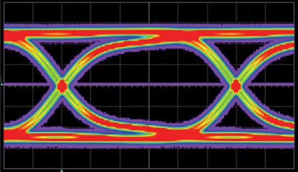
The dielectric constant, or relative permittivity, of an epoxy resin determines the effective capacitance per unit length in transmission lines, directly influencing signal velocity and impedance. For high frequency epoxy resin PCB applications, a stable dielectric constant epoxy resin is crucial, as variations with frequency or temperature can distort timing and introduce crosstalk. Low loss epoxy resin achieves this stability through controlled resin-glass interfaces that limit moisture absorption and minimize frequency-dependent shifts. Dissipation factor, or tan delta, quantifies energy loss per cycle, with lower values essential for preserving signal amplitude in long traces or high-data-rate links. Signal integrity epoxy resin performance hinges on these properties, as elevated losses manifest as eye diagram closure or bit error rates exceeding specifications. According to IPC-4101, base materials must meet defined electrical tolerances to ensure consistency across production batches.
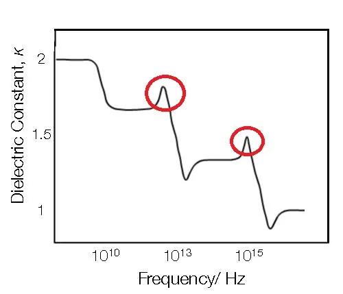
Material uniformity also affects surface roughness, which contributes to conductor losses via skin effect at microwave frequencies. Engineers evaluate these via split-post dielectric resonators or stripline methods during qualification. Resin content in prepregs influences flow during lamination, impacting void formation and final Dk homogeneity. Selecting dielectric constant epoxy resin with matched resin and reinforcement permittivities prevents anisotropy that skews impedance calculations.
Design Considerations for Signal Integrity and Impedance Control
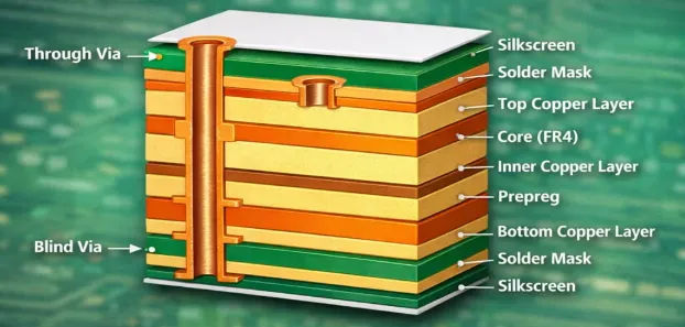
Impedance control epoxy resin design begins with precise stackup modeling, where trace width, spacing, and dielectric thickness are adjusted to achieve target characteristic impedance, typically 50 ohms for single-ended RF lines. Variations in low loss epoxy resin Dk necessitate field solver simulations accounting for frequency dispersion and manufacturing tolerances. Signal reflections arise from discontinuities like vias or bends, so impedance control epoxy resin strategies include back-drilling excess stub lengths and using blind or buried vias. Ground plane proximity minimizes radiation, but epoxy's higher loss requires wider traces to offset conductor attenuation. In multilayer high frequency epoxy resin PCB layouts, reference plane partitioning isolates analog and digital sections to curb crosstalk.
Thermal management integrates copper pours and vias for heat spreading, as epoxy resins exhibit Tg around 170-180°C, beyond which Dk rises sharply. Per IPC-2221, design rules specify clearance and creepage for high-voltage high-frequency operation, preventing arcing under peak fields. Vias demand stitching around high-speed nets to maintain return paths, preserving signal integrity epoxy resin. Fabricators test impedance post-etching using time-domain reflectometry, feeding data back for design refinement.
Material Selection Best Practices
Selecting low loss epoxy resin involves balancing electrical needs against mechanical and thermal demands. Prioritize materials with Df below standard epoxies at operating frequencies, verified through datasheet curves spanning 1 MHz to 10 GHz. Dielectric constant epoxy resin stability over -55°C to 125°C ensures performance in avionics or automotive radar. Coefficient of thermal expansion matching between resin, copper, and components averts warpage, tested via ASTM methods during qualification. Cost considerations favor epoxy over ceramics for frequencies up to several GHz, where signal integrity epoxy resin suffices without excessive loss.
Hybrid stackups pair low loss epoxy resin cores with standard prepregs for outer layers, optimizing via reliability. IPC-6012 outlines qualification for rigid boards, mandating electrical tests like propagation delay and insertion loss. Procurement specs include resin content percentages for lamination predictability. Environmental factors like humidity absorption guide selection, as swollen epoxies elevate Dk and Df.
Troubleshooting Common Challenges in High-Frequency Epoxy PCBs
Signal degradation often traces to inadequate impedance control epoxy resin, manifesting as ringing on oscilloscopes. Calibrate models with fabricated coupons to correlate simulation and measurement. Warpage from CTE mismatch warps traces, altering Dk locally; mitigate via symmetric stackups and constrained lamination. Delamination at interfaces signals poor prepreg flow, addressed by adjusting press cycles per material guidelines. High insertion loss points to rough copper or high Df; specify low-profile foil and verify with vector network analyzer sweeps.
Moisture preconditioning per JEDEC J-STD-020 reveals absorption effects on signal integrity epoxy resin. Fabricator audits ensure compliance, closing the loop from design to assembly.
Conclusion
Epoxy resin PCBs remain viable for high-frequency applications through judicious selection of low loss epoxy resin and rigorous design practices. Stable dielectric constant epoxy resin, minimal dissipation, and precise impedance control epoxy resin form the triad for robust signal integrity epoxy resin. Adhering to standards like IPC-4101, IPC-2221, and IPC-6012 guarantees manufacturability and reliability. Engineers benefit from structured material evaluation and simulation-driven layouts, extending epoxy's utility into GHz regimes. Future iterations will refine these for even higher speeds, maintaining the material's economic edge.
FAQs
QX: What makes low loss epoxy resin suitable for high frequency epoxy resin PCB designs?
AX: Low loss epoxy resin features a reduced dissipation factor, minimizing signal attenuation in RF and microwave circuits. This property preserves waveform integrity over longer traces compared to standard epoxies. Selection focuses on frequency-specific data, ensuring compatibility with impedance control requirements. Practical testing confirms performance under operational conditions.
QX: How does dielectric constant epoxy resin impact signal integrity epoxy resin?
AX: Dielectric constant epoxy resin governs signal propagation speed and crosstalk levels in multilayer boards. Instability with frequency leads to timing skew and reflections. Engineers specify materials with low variation for consistent performance. This directly supports reliable high-speed data transmission.
QX: Why is impedance control epoxy resin critical in high-frequency applications?
AX: Impedance control epoxy resin prevents reflections that degrade eye patterns and increase bit errors. It requires precise stackup dimensions and material Dk uniformity. Simulations guide trace geometries for 50-ohm targets. Post-fabrication TDR verification ensures compliance.
QX: What role do standards play in high frequency epoxy resin PCB material selection?
AX: Standards like IPC-4101 define electrical and mechanical specs for base materials, aiding qualification. They standardize testing for Dk, Df, and thermal properties. Compliance reduces variability across suppliers. This framework supports scalable production for demanding applications.
FAQs
Q1: What makes low loss epoxy resin suitable for high frequency epoxy resin PCB designs?
A1: Low loss epoxy resin features a reduced dissipation factor, minimizing signal attenuation in RF and microwave circuits. This property preserves waveform integrity over longer traces compared to standard epoxies. Selection focuses on frequency-specific data, ensuring compatibility with impedance control requirements. Practical testing confirms performance under operational conditions.
Q2: How does dielectric constant epoxy resin impact signal integrity epoxy resin?
A2: Dielectric constant epoxy resin governs signal propagation speed and crosstalk levels in multilayer boards. Instability with frequency leads to timing skew and reflections. Engineers specify materials with low variation for consistent performance. This directly supports reliable high-speed data transmission.
Q3: Why is impedance control epoxy resin critical in high-frequency applications?
A3: Impedance control epoxy resin prevents reflections that degrade eye patterns and increase bit errors. It requires precise stackup dimensions and material Dk uniformity. Simulations guide trace geometries for 50-ohm targets. Post-fabrication TDR verification ensures compliance.
Q4: What role do standards play in high frequency epoxy resin PCB material selection?
A4: Standards like IPC-4101 define electrical and mechanical specs for base materials, aiding qualification. They standardize testing for Dk, Df, and thermal properties. Compliance reduces variability across suppliers. This framework supports scalable production for demanding applications.
References
IPC-4101E — Specification for Base Materials for Rigid and Multilayer Printed Boards. IPC, 2017
IPC-2221A — Generic Standard on Printed Board Design. IPC, 2009
IPC-6012E — Qualification and Performance Specification for Rigid Printed Boards. IPC, 2017


