Introduction
Rigid-flex printed circuit boards combine the structural integrity of rigid substrates with the adaptability of flexible circuits, making them ideal for demanding environments. These hybrid boards enable compact designs that withstand mechanical stress, vibration, and thermal cycling common in high-reliability systems. Engineers in aerospace, medical, and military sectors increasingly turn to rigid-flex PCB applications to meet space constraints and performance requirements. The advantages of rigid-flex PCBs extend beyond size reduction, offering enhanced signal integrity and reduced assembly failures. This article explores their technical benefits, materials, design strategies, and manufacturing insights tailored for electric engineers focused on reliability.
What Are Rigid-Flex PCBs and Why They Matter in High-Reliability Systems
Rigid-flex PCBs integrate rigid sections, typically made from fiberglass-reinforced epoxy, with flexible sections using polyimide films. The rigid portions support components and provide mechanical stability, while flexible tails or regions allow bending and folding to fit irregular shapes. In high-reliability systems, such as avionics or implantable medical devices, these boards eliminate bulky wiring harnesses and connectors that introduce failure points. Vibration and shock in military equipment or aircraft demand boards that maintain electrical continuity despite dynamic flexing. Rigid-flex designs thus support 3D packaging, optimizing volume in enclosures where traditional rigid boards fall short. Their relevance grows as systems miniaturize without sacrificing durability.
High-reliability applications prioritize mean time between failures (MTBF), where rigid-flex PCBs excel by minimizing interconnects. For instance, in aerospace, weight savings translate directly to fuel efficiency, while in medical wearables, flexibility aids patient comfort. These boards address the limitations of pure rigid or flex circuits, blending both for optimal performance. Engineers value their ability to route signals through bends without degradation, crucial for high-speed data in radar systems. Overall, rigid-flex PCB applications prove essential where reliability under harsh conditions is non-negotiable.
Key Advantages of Rigid-Flex PCBs
One primary advantage of rigid-flex PCBs lies in space and weight optimization, critical for portable high-reliability devices. By folding flexible sections, designers achieve denser packing than multi-board assemblies with connectors. This reduces overall system mass, vital in aerospace and military gear subjected to g-forces. Fewer solder joints mean lower risk of fatigue cracks from thermal expansion mismatches. Reliability improves as continuous copper traces maintain impedance control across transitions.
Another benefit is superior vibration resistance. Flexible polyimide layers absorb shocks better than rigid laminates, preventing delamination in automotive or defense systems. Signal integrity benefits from shorter paths, reducing crosstalk and attenuation in high-frequency applications. Assembly simplifies, cutting labor costs and errors associated with wire bonding. In medical imaging equipment, these advantages ensure consistent performance during prolonged use.
Rigid-flex PCBs also enhance thermal management. The thinner profile dissipates heat more effectively than stacked rigid boards, aiding components in confined spaces. Their durability supports repeated flex cycles without cracking, ideal for deployable structures in satellites. Cost savings emerge over lifecycle through fewer field replacements. These advantages position rigid-flex as a go-to for engineers targeting long-term system uptime.
Rigid-Flex PCB Materials
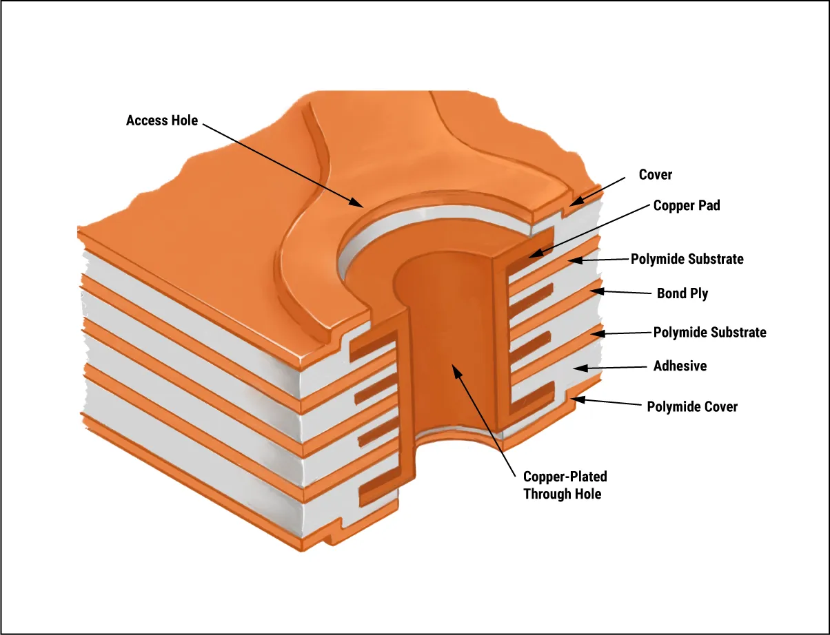
Selecting appropriate rigid-flex PCB materials ensures compatibility between rigid and flex sections, preventing issues like warping during lamination. Polyimide films serve as the core for flexible areas due to their high thermal stability and low moisture absorption. These films, often 25 to 50 microns thick, pair with rolled annealed copper for ductility during bending. Adhesives, such as acrylic or modified epoxy, bond layers but must match coefficients of thermal expansion (CTE) to avoid stresses.
Rigid sections typically use FR-4 epoxy glass for cost-effectiveness and rigidity, but high-Tg variants suit elevated temperatures. Coverlays of polyimide protect flex traces, while stiffeners reinforce component mounting areas. Adhesiveless constructions minimize thickness and improve bend radius by directly laminating copper to polyimide. Material choices directly impact flex life; polyimide withstands over 1000 cycles at tight radii.
Engineers must verify material qualifications per industry standards to guarantee performance. Polyimide's dielectric strength exceeds 200 V/mil, supporting high-voltage medical applications. Coverlay adhesives require precise cure cycles to prevent voids. Overall, rigid-flex PCB materials balance flexibility, strength, and environmental resistance for sustained reliability.
Designing Rigid-Flex PCBs for Reliability
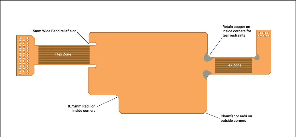
Designing rigid-flex PCBs for reliability starts with stackup planning, ensuring symmetry to minimize warpage. Transition zones between rigid and flex demand gradual stiffener tapers to distribute stresses evenly. IPC-2223 outlines guidelines for bend radii, typically 10 times the copper thickness to avoid cracking. Vias in flex areas should use filled or staggered configurations to withstand folding.
Trace routing in flexible sections favors curved paths over sharp angles, reducing strain concentrations. Ground planes on flex layers shield signals and provide mechanical support. Simulate dynamic flexing to predict fatigue, accounting for operational bend counts. Component placement avoids flex tails, concentrating on rigid islands for secure soldering.
Material CTE matching prevents delamination; polyimide's 20-30 ppm/°C aligns better with copper than some epoxies. Outline rigid-flex boundaries early, defining fold lines precisely. IPC-6013 specifies qualification tests like thermal cycling and flex endurance. These practices yield boards enduring -55°C to 125°C without failure.
Thermal vias and heat sinks integrate seamlessly in rigid areas, dissipating power from high-reliability ICs. Impedance control requires consistent dielectric thicknesses across transitions. Design rule checks must include flex-specific parameters like tear-drop pads. Prototyping validates assumptions, iterating on stackups for optimal reliability.
Rigid-Flex PCB Manufacturing Considerations
Rigid-flex PCB manufacturing involves sequential lamination, building rigid cores around flex cores. Flex circuits form first, with copper etched and coverlay applied, then bonded to rigid multilayers using prepregs. Alignment fiducials ensure layer registration during pressing, critical for high-density interconnects. Challenges arise from CTE differences, causing bow in panels exceeding 0.75%.
Controlled impedance demands precise etch control in flex copper, often thinner at 18 microns. Outer layer imaging post-lamination avoids flex distortion. Solder mask on rigid sections protects while flex coverlays seal traces. Manufacturing tolerances tighten to ±0.05 mm for bend lines.
Testing per IPC-6013 includes cyclic bending, where boards endure 1000 cycles at specified radii without opens. Peel strength verifies adhesive bonds, targeting 1.5 N/mm minimum. Flying probe electrical tests confirm continuity post-flex. These steps mitigate risks in high-reliability production.
Scalability favors panelized designs, but handling flex tails requires fixtures. Bake-out removes moisture before pressing, preventing pops. Final profiling uses routing for rigid edges and laser for flex outlines. Quality control employs cross-sectioning to inspect transitions.
Case Insights: Applications in Harsh Environments
In aerospace, rigid-flex PCB applications connect sensors in wing structures, flexing with airframe movements. Military wearables use them for conformal fitting under body armor, resisting sweat and impacts. Medical endoscopes benefit from slim profiles navigating tight anatomies. Automotive ADAS modules endure engine bay vibrations.
Common pitfalls include over-flexing transitions, addressed by reinforcing with frames. Field data shows rigid-flex assemblies outlasting wired equivalents by factors of 2-3 in MTBF. Engineers troubleshoot via thermal imaging for hot spots at bends.
Conclusion
Rigid-flex PCBs deliver unmatched benefits in high-reliability systems through space efficiency, vibration tolerance, and interconnect reliability. Strategic material selection and design per IPC guidelines ensure longevity. Manufacturing precision overcomes complexities, yielding robust boards. For electric engineers, integrating rigid-flex elevates system performance in critical applications. Future advancements will further refine these hybrids for emerging challenges.
FAQs
Q1: What are the main rigid-flex PCB applications in high-reliability systems?
A1: Rigid-flex PCB applications include aerospace avionics, military wearables, and medical implants where space, weight, and durability matter. They replace wiring in vibrating environments, reducing failures. Design flexibility suits irregular shapes, maintaining signal quality. Standards like IPC-2223 guide implementations for optimal performance.
Q2: What are the key advantages of rigid-flex PCBs over traditional rigid boards?
A2: Advantages of rigid-flex PCBs encompass weight reduction, fewer connectors, and better shock absorption via polyimide flex sections. They enable 3D layouts impossible with rigid boards alone. Reliability boosts from continuous traces minimize fatigue. Ideal for compact high-reliability designs enduring thermal cycles.
Q3: How to approach designing rigid-flex PCBs for reliability?
A3: Designing rigid-flex PCBs for reliability involves symmetric stackups, CTE-matched materials, and minimum bend radii per IPC-2223. Route traces curved in flex areas, avoid vias there. Simulate flex cycles and prototype transitions. This prevents delamination and ensures high MTBF in harsh conditions.
Q4: What materials are used in rigid-flex PCB manufacturing?
A4: Rigid-flex PCB manufacturing employs polyimide for flex cores, FR-4 for rigid sections, and acrylic/epoxy adhesives for bonding. Copper foils suit ductility needs. Coverlays protect flex traces. Material choices focus on thermal stability and low CTE mismatch for durable laminates.
References
IPC-2223 — Design Standard for Flex and Rigid-Flex Circuits. IPC
IPC-6013 — Qualification and Performance Specification for Flexible and Rigid-Flex Printed Boards. IPC
IPC-A-600 — Acceptability of Printed Boards. IPC


