Introduction
Copper pour, often referred to as ground pour, involves filling unused areas on printed circuit board layers with copper connected to a reference net, typically ground. While traditionally applied to dedicated plane layers, applying copper pour to routing layers offers distinct advantages in modern PCB designs. Routing layers, primarily used for signal traces, benefit from this technique by enhancing electromagnetic compatibility and signal integrity. Engineers face increasing challenges with high-speed signals and stringent EMI specifications, making copper pour a practical solution. This article explores the engineering rationale, implementation strategies, and performance benefits of using copper pour on routing layers. By integrating it thoughtfully, designers can achieve better compliance and reliability without adding layers.
What Is Copper Pour on Routing Layers and Why It Matters
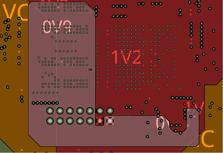
Copper pour on routing layers means creating contiguous or hatched copper regions around signal traces on layers not dedicated solely to power or ground planes. These pours connect to the ground net via vias or direct ties, forming a local reference for nearby signals. Unlike full planes, this approach adapts to the irregular spacing of traces on routing layers. It matters because high-frequency signals, such as clock lines, demand low-impedance return paths to minimize radiation and crosstalk. Without adequate ground referencing, traces act as antennas, violating EMI specifications in applications like telecommunications and computing. Ground pour thus bridges the gap between cost-effective two-layer boards and multilayer performance.
In dense designs, routing layers often lack sufficient ground proximity, leading to uncontrolled impedance and increased emissions. Copper pour mitigates this by providing a distributed ground structure, essential for meeting regulatory EMI limits. For electric engineers, this technique supports faster prototyping while aligning with performance goals. It also aids thermal management by spreading heat from traces. Ultimately, it enables compliance without redesigning stackups.
Technical Principles Behind Copper Pour Benefits
The core principle revolves around providing a low-inductance return path for signal currents. On routing layers, signals propagate with return currents ideally mirroring on an adjacent ground plane, but pour simulates this locally. This reduces loop inductance, cutting radiated emissions proportional to the square of the frequency. For clock signals operating above 100 MHz, loop areas must shrink below lambda/20, where lambda is the wavelength. Ground pour, when stitched with vias every few millimeters, approximates a solid plane, stabilizing characteristic impedance.
Electromagnetic interference arises from differential mode currents creating magnetic fields. Copper pour shields these by offering equipotential surfaces that confine fields between trace and pour. Stitching vias prevent slot antennas, where gaps resonate at harmonics. Simulations show 10-20 dB emission reduction with proper pours, though exact gains depend on frequency and geometry. Fabric uniformity improves too, as balanced copper distribution minimizes warpage during lamination, per IPC-6012 performance specs.
Crosstalk between parallel traces drops with ground pour acting as a guard. Far-end coupling reduces by increasing capacitance to ground, while near-end coupling benefits from field termination. For mixed-signal boards, isolating analog pours from digital prevents noise coupling. Thermal effects include better heat sinking for power traces embedded in routing layers. Overall, these mechanisms justify pours beyond aesthetics.
EMI Reduction and Compliance with Specifications
EMI specifications demand radiated and conducted limits, often per class B or better for consumer electronics. Copper pour on routing layers excels here by lowering board-edge emissions from clock harmonics. Without pour, edge traces radiate freely; pour absorbs and returns energy locally. Engineering analysis confirms pours reduce peak emissions by distributing ground impedance evenly.
Via stitching density is critical: space vias at less than one-tenth the shortest wavelength to block higher-order modes. For a 1 GHz clock, lambda/10 is about 30 mm in FR-4, but tighter for safety. Ground pour also aids susceptibility by shunting external fields. Compliance testing shows boards with pours passing margins easier, especially outer layers exposed to probes.
In multilayer boards, routing layer pours complement inner planes, extending shielding to surfaces. This hybrid approach suits mid-range designs avoiding full six-layer costs. Logical placement prioritizes high-speed nets near pours.
Practical Best Practices for Implementation
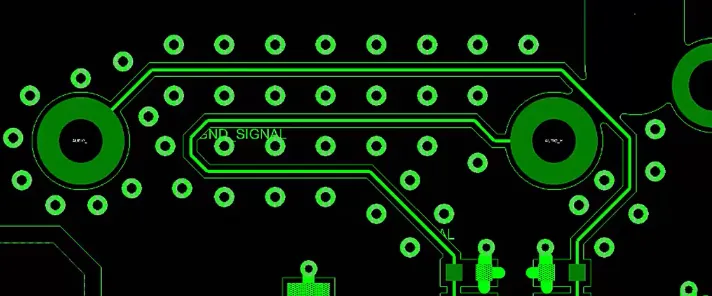
Start with design rules enforcing minimum clearances between pour and unrelated traces, typically 0.15 mm or more, aligned with IPC-2221 conductor spacing guidelines. Connect pours to ground net islands via thermals or direct pours, avoiding isolated regions that float and couple noise. Use hatched pours for flexibility in etching, reducing stress on thin cores.
Stitch outer layer pours to inner grounds with blind or through vias at 5-10 mm grids, denser near clocks. Route return paths under signals whenever possible, using pour to fill gaps. Simulate impedance pre-layout to verify 50-ohm targets. During review, check pour connectivity with DRC nets.
Fabrication benefits from pours balancing copper density to 50-70% per layer, preventing plating thickness variations. Avoid pours under sensitive passives to prevent parasitics. Test prototypes with near-field probes to validate EMI improvements.
Challenges and Mitigation Strategies
Improper pours can worsen EMI if vias are sparse, creating resonant slots. Mitigate by calculating max spacing from highest clock frequency: spacing < c/(10*f*epsilon_r^{0.5}), where c is light speed. Hatching reduces this risk versus solid fills. Warpage from asymmetric copper demands symmetric pours top-to-bottom.
In high-current areas, pours add parallel paths but require width checks per current-carrying capacity rules. For RF, avoid pours near antennas to prevent detuning. Logical troubleshooting involves scoping emissions pre/post-pour.
Case Insights from High-Speed Designs
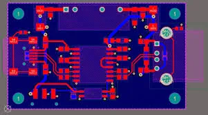
Consider a four-layer board with clock at 500 MHz on top routing layer. Without pour, emissions spiked at 1.5 GHz harmonic. Adding ground pour with 8 mm stitching dropped peaks 15 dB, passing specs. Stackup had signal-ground-signal-power, where top pour tied to inner ground.
Another insight: two-layer boards gain most, turning signal-signal into pseudo signal-ground. Clocks routed mid-board benefited least without stitching. These cases underscore pours as targeted fixes.
Conclusion
Copper pour on routing layers strengthens PCB performance through EMI control, impedance stability, and fabrication balance. For electric engineers handling clock-heavy designs, it delivers measurable gains against EMI specifications without stackup changes. Adhering to stitching, clearances, and symmetry ensures benefits outweigh risks. Ground pour evolves routing layers into functional hybrids, optimizing cost and compliance. Integrate it strategically for robust, high-speed boards.
FAQs
Q1: What role does copper pour play in meeting EMI specifications on routing layers?
A1: Copper pour on routing layers provides a local ground reference, reducing loop areas and radiated emissions from signals like clocks. Stitching vias connect it to planes, preventing slot resonances and ensuring fields stay confined. This aligns with design practices for compliance, often yielding 10 dB or more reduction in peaks. Proper density and clearance maintain integrity without parasitics.
Q2: How does ground pour affect clock signal integrity?
A2: Ground pour stabilizes return paths for clock traces on routing layers, controlling impedance and minimizing jitter. It lowers crosstalk by terminating fields locally, crucial at high frequencies. Vias every lambda/20 ensure plane-like behavior. Simulations confirm flatter eye diagrams post-implementation. Balance with hatches avoids etching issues.
Q3: Should copper pour be used on all routing layers?
A3: Use copper pour selectively on outer routing layers for EMI shielding and on inner ones for balance. Prioritize near high-speed nets or edges. Avoid under RF sections or where it skews impedance. IPC-2221 spacing rules guide clearances. Test iteratively for optimal results.
Q4: What is the impact of stitching vias in copper pour?
A4: Stitching vias tie routing layer pours to ground planes, distributing impedance and blocking EMI leakage. Space at 1/10 wavelength of the highest clock for effectiveness. This prevents pours acting as antennas. Denser grids near edges enhance shielding. Verify connectivity in DRC.
References
IPC-2221B — Generic Standard on Printed Board Design. IPC, 2003
IPC-6012F — Qualification and Performance Specification for Rigid Printed Boards. IPC, 2023
IPC-A-600K — Acceptability of Printed Boards. IPC, 2020


