Introduction
Printed circuit boards form the foundation of modern electronics, powering everything from consumer devices to industrial systems. When faults occur, electric engineers must quickly identify and resolve issues to avoid costly downtime and ensure reliability. This PCB troubleshooting tools guide covers essential equipment for fault diagnosis, from detecting shorts and open circuits to repairing damaged PCBs. Engineers rely on a combination of basic and advanced PCB fault diagnosis equipment to pinpoint problems efficiently. Understanding the right tools and techniques saves time and reduces the risk of further damage during testing. By following structured methods, professionals can restore functionality while adhering to industry best practices.
Why PCB Troubleshooting Matters in Electronics Engineering
PCB faults can stem from manufacturing defects, environmental stress, or assembly errors, leading to intermittent or complete failures. Effective troubleshooting minimizes production delays and extends board lifespan, which is critical in high-volume applications. For electric engineers, mastering PCB testing tools for shorts and open circuits ensures compliance with quality standards and improves overall system performance. Delays in diagnosis often cascade into larger issues, such as supply chain disruptions or field returns. Investing time in a systematic approach using reliable PCB repair tools list enhances diagnostic accuracy. Ultimately, proficient troubleshooting supports innovation by allowing engineers to iterate designs with confidence.
Common PCB Faults and Their Underlying Causes
Short circuits represent one of the most frequent issues, where unintended low-resistance paths cause excessive current flow and potential overheating. Open circuits occur when traces break or solder joints fail, interrupting signal paths and halting operations. Poor soldering, such as cold joints or insufficient wetting, often leads to intermittent connectivity problems under vibration or thermal cycling. Component failures, including cracked capacitors or degraded resistors, exacerbate these faults during operation. Manufacturing variations, like via misalignment, contribute to hidden defects that surface post-assembly. Recognizing these patterns guides engineers toward targeted diagnosis using appropriate PCB troubleshooting multimeter settings and other equipment.
Essential PCB Troubleshooting Tools
A well-equipped workbench starts with versatile instruments tailored for precise measurements. Electric engineers benefit from tools that cover electrical, thermal, and visual inspections without requiring extensive setup. Selecting the best tools for PCB rework involves balancing portability, accuracy, and compatibility with various board types. These instruments form the core of any PCB fault diagnosis equipment kit. Below, key tools are detailed with practical applications.
Related Reading: Essential Tools for DIY ECU PCB Repair: A Comprehensive Guide
Digital Multimeter for Basic Electrical Checks
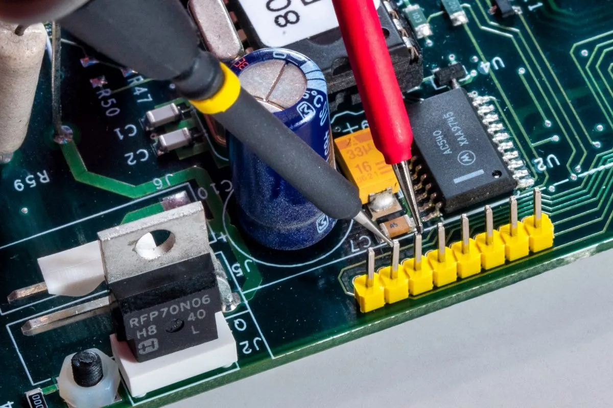
The digital multimeter stands as the cornerstone of PCB troubleshooting, offering modes for voltage, resistance, continuity, and diode testing. For finding open circuits on PCBs, set the multimeter to continuity mode, where a beep indicates connection and silence signals a break. To detect shorts, switch to low-range ohms; readings near zero ohms between non-adjacent nets suggest a fault. Always power off the board and discharge capacitors before probing to avoid false readings or damage. Engineers adjust PCB troubleshooting multimeter settings based on the circuit section, using diode mode for semiconductor junctions. This tool excels in rapid verification of power rails and component values.
Oscilloscope for Signal Integrity Analysis
Oscilloscopes capture waveform details, revealing timing issues, noise, or distortion invisible to multimeters. Connect probes to suspect signals and trigger on edges to isolate anomalies like ringing or overshoot. For dynamic faults, use multiple channels to compare inputs and outputs simultaneously. Persistence mode helps spot intermittent glitches during powered operation. This equipment proves invaluable for high-speed digital circuits where static tests fall short. Proper grounding minimizes probe-induced artifacts during measurements.
Thermal Imaging Camera for Hotspot Detection
Thermal cameras visualize heat signatures, identifying shorts or failing components through elevated temperatures. Scan powered boards from a safe distance, noting hotspots exceeding normal operating ranges by significant margins. Correlate thermal data with schematics to prioritize invasive inspections. This non-contact method accelerates triage in complex assemblies. Combine with airflow control for accurate readings unaffected by ambient conditions. Engineers use it early in the process to avoid unnecessary electrical probing.

Stereo Microscope for Visual and Fine Work
Magnification tools like stereo microscopes reveal microcracks, solder bridges, or contamination under 10x to 50x zoom. LED illumination enhances contrast for inspecting ball grid array pads or fine-pitch components. Polarized light filters reduce glare from shiny surfaces during fault hunting. This visual aid supports precise rework preparation by confirming defect locations. Integrate with a stable stand for hands-free operation during extended sessions.
Rework Stations for Repair Operations
Hot air rework stations and precision soldering irons enable component removal and replacement. Control temperature profiles to prevent delamination or pad lift. Use flux and no-clean solder for clean joints compliant with assembly standards. These tools address physical damage after diagnosis confirms the issue.
Related Reading: The Ultimate Guide to PCB Rework Stations: Choosing the Right Equipment for Repair
Step-by-Step Guide to Diagnosing PCB Faults
Begin with a thorough visual inspection under magnification for obvious damage like burnt marks or displaced parts. Power the board with a current-limited supply and monitor for excessive draw, indicating shorts. Use the multimeter across power and ground planes; low resistance flags a problem. For open circuits, trace nets systematically from known good points outward. Employ the oscilloscope on powered signals to check logic levels and edges. If thermal anomalies appear, isolate the section before deeper probing. Document findings to guide repair.
To hunt shorts efficiently, divide the board into zones and test pairwise between nets. Inject a low-voltage signal into the shorted path and probe with the multimeter in AC volts mode to trace the path. For opens, continuity beeps narrowing down breaks, supplemented by resistance trends along traces. Always reference the schematic or netlist for expected connectivity.
Best Practices for Repairing Damaged PCBs
Preparation involves clean workspaces and ESD protection to prevent secondary faults. Follow procedures in IPC-7711/7721 for rework, ensuring controlled heating to avoid collateral damage. Desolder components with wick or hot air, then inspect pads per IPC-A-610 criteria for acceptability. Apply fresh solder and flux, verifying joints meet J-STD-001 requirements for fillet formation and wetting. Post-repair, functional test the board under load. Bake out moisture if exposed to humidity before reassembly.
Clean residues with isopropyl alcohol and inspect under microscope. Test repaired sections with multimeter before full power-up. Iterate if faults persist, checking for lifted traces or via failures.
Advanced Techniques for Complex Boards
For multilayer boards, boundary scan or flying probe testers provide automated net testing beyond manual limits. X-ray inspection reveals inner layer shorts without disassembly. Combine data logging from oscilloscopes with thermal maps for root cause analysis. Simulate faults in software models pre-repair to validate fixes.
Conclusion
Mastering PCB troubleshooting tools equips electric engineers to handle faults from simple shorts to intricate signal issues. A systematic approach using multimeters, scopes, and thermal cameras ensures accurate diagnosis. Repair with precision following standards like IPC-7711/7721 yields reliable results. Integrating these practices into workflows boosts efficiency and board longevity. Stay vigilant with regular tool calibration and documentation for consistent outcomes.
FAQs
Q1: What are the essential PCB testing tools for shorts in a troubleshooting toolkit?
A1: Key PCB fault diagnosis equipment includes a digital multimeter set to low ohms or continuity mode to detect low-resistance paths between nets. Thermal imaging cameras spot overheating indicative of shorts. Visual aids like microscopes reveal solder bridges. Start with power-off resistance checks across power rails. This combination forms a comprehensive PCB troubleshooting tools guide for rapid identification.
Q2: How do you use multimeter settings for finding open circuits on PCBs?
A2: Set the multimeter to continuity or high-range ohms; probe along traces from source to load. No beep or infinite resistance confirms an open. Test component leads separately after removal if needed. Power off and isolate sections to avoid parallel paths skewing results. Verify with voltage checks on powered board post-repair.
Q3: What is the best PCB repair tools list for damaged boards?
A3: Core items include hot air rework stations, precision soldering irons, desoldering wicks, flux, and microscopes. Use temperature-controlled tools to prevent further damage. Follow IPC-7711/7721 guidelines for procedures. Include multimeters for verification and thermal cameras for monitoring. This setup supports repairing damaged PCBs effectively.
Q4: Which tools help in PCB rework for electric engineers?
A4: The best tools for PCB rework feature hot air pencils for SMD removal, stereo microscopes for precision, and soldering stations with fine tips. Thermal cameras guide temperature application. Multimeters confirm post-rework continuity. Adhere to J-STD-001 for joint quality. These enable professional repairs without compromising integrity.
References
IPC-7711/7721C — Rework, Modification and Repair of Electronic Assemblies. IPC.
IPC-A-610H — Acceptability of Electronic Assemblies. IPC, 2019.
J-STD-001J — Requirements for Soldered Electrical and Electronic Assemblies. IPC, 2025.


