Introduction
Ceramic PCB layout plays a crucial role in ensuring reliable performance for electronic hobbyists tackling projects that demand high thermal management and durability. Unlike standard FR4 boards, ceramic substrates offer superior heat dissipation, making them ideal for simple setups like LED drivers or sensor modules where overheating can ruin functionality. For beginners in PCB design for hobbyists, understanding ceramic PCB layout starts with grasping basic principles to avoid common pitfalls such as cracking or poor solder joints. This tutorial focuses on simple PCB layout techniques tailored for hobbyist-level projects, emphasizing practical steps without complex multilayer stacks. By following structured guidelines, hobbyists can achieve professional results in their ceramic PCB tutorial explorations. Key considerations include material handling, trace routing, and thermal paths to keep designs straightforward and effective.
What Are Ceramic PCBs and Why They Matter for Hobbyists
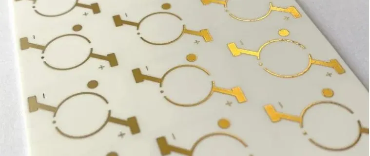
Ceramic printed circuit boards use insulating ceramic materials as the base substrate, providing excellent thermal conductivity and electrical isolation compared to organic laminates. Common ceramics like alumina excel in applications requiring operation at elevated temperatures, which suits hobbyist projects involving power components or harsh environments. In simple PCB layout scenarios, these boards prevent hotspots that plague FR4 designs under moderate loads, extending component life. Hobbyists benefit from their dimensional stability, reducing warpage issues during assembly. For beginner PCB design, ceramic PCBs matter because they enable reliable prototypes for experiments like motor controls or amplifiers without frequent failures. Their relevance grows as projects scale from breadboards to custom boards, offering a step up in performance.
The choice of ceramic over traditional materials hinges on project needs, such as dissipating heat from a few watts effectively. Electrical properties include low dielectric loss, supporting high-frequency signals in basic RF hobby circuits. Mechanical strength resists vibration better than plastics, ideal for portable gadgets. Cost remains accessible for small runs, fitting hobby budgets. Overall, ceramic PCB layout empowers hobbyists to explore advanced thermal designs in simple contexts.
Key Technical Principles of Ceramic PCB Layout
Ceramic substrates feature a coefficient of thermal expansion (CTE) around 6-8 ppm/°C, much lower than silicon chips at 2-4 ppm/°C or FR4 at 15-20 ppm/°C, demanding careful component matching to prevent stress cracks. Layout must prioritize uniform heat distribution through wide traces and ground planes, leveraging the substrate's inherent conductivity of 20-200 W/mK. Vias, if used sparingly in simple designs, require filled or plugged types to maintain structural integrity due to the brittle nature of ceramics. Conductor layers, typically screen-printed or direct-bonded copper, need precise patterning to avoid delamination under thermal cycling. Adhering to IPC-A-600K acceptability criteria ensures surface finish quality for soldering reliability. These principles form the foundation of effective ceramic PCB layout.
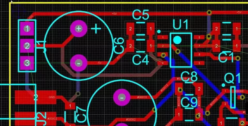
Trace routing follows minimum widths based on current carrying capacity, often starting at 0.2 mm for low-power hobby circuits to minimize resistance. Spacing prevents shorts, typically 0.15 mm or more, considering manufacturing tolerances. Pad geometries match component footprints exactly, with solder mask openings adjusted for ceramic's smooth surface. Multilayer ceramics, though rare for beginners, stack via precise alignment to control impedance. Thermal vias under power devices channel heat directly into the substrate, enhancing dissipation without fans. Understanding these mechanisms allows hobbyists to optimize simple PCB layouts intuitively.
Related Reading: Ceramic PCB vs. FR-4: Choosing the Right Material for Your High-Frequency Design
Brittleness necessitates avoiding sharp corners in cutouts or slots, using radii greater than 0.5 mm to reduce fracture risk during handling. Edge plating provides robustness for connectors in hobby enclosures. Solder joint integrity relies on compatible metallizations, tested per JEDEC J-STD-020E for reflow sensitivity. Layout symmetry balances mechanical stresses, preventing bow or twist. These technical aspects ensure ceramic PCBs withstand assembly processes common in home workshops.
Best Practices for Simple Ceramic PCB Layout
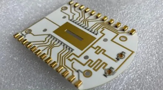
Start with a single-layer design for beginner PCB design, placing high-heat components centrally to exploit radial heat spreading. Use copper thickness of 0.5-1 oz for most hobby currents, calculating widths via standard formulas to limit temperature rise below 20°C. Ground pours cover unused areas, connecting to pads with multiple vias if needed, to form a heat sink. Component orientation aligns CTE mismatches along the board's longer axis, minimizing shear forces. Prototype on small panels, say 50x50 mm, to control costs and test fits. These practices streamline ceramic PCB layout for reliable hobby outcomes.
Software-independent planning involves sketching on graph paper first, marking thermal paths from sources to edges. Mount heatsinks directly on ceramic surfaces using thermal interface materials, avoiding adhesives that trap heat. For soldering, preheat boards gradually to 100-150°C to match low moisture absorption. Inspect for defects like voids using visual aids, aligning with IPC-6012E performance specs. Iterate designs by simulating mentally or with basic calculators for trace temps. Hobbyists find these steps transform simple PCB layout into robust solutions.
Edge margins exceed 5 mm from cuts to board edges, safeguarding traces from chipping. Label silkscreen clearly with 0.1 mm height fonts for troubleshooting. Test points on non-critical nets aid debugging without compromising layout. For power hobby projects, integrate fuses near inputs. Batch small quantities to refine based on real builds. Consistent application yields ceramic PCB tutorials that hobbyists revisit confidently.
Related Reading: Thermal Management Secrets: Optimizing Heat Dissipation with Ceramic PCBs
Troubleshooting Common Layout Issues in Ceramic PCBs
Warpage arises from asymmetric copper distribution, countered by balancing pours across layers or using dummy patterns. Measure deflection with straightedges; values under 0.75% of dimension comply with standards. Cracked traces often stem from excessive flexing; handle with tweezers and store flat. Solder wicking up vias clogs paths, fixed by tenting or back-drilling in prototypes. Overheating signals poor thermal planning; add more ground plane or widen paths iteratively. Logical diagnosis keeps hobby projects on track.
Delamination occurs from flux residue; clean ultrasonically post-reflow. Component tombstoning links to CTE mismatch; select low-expansion parts or add standoffs. Short circuits from debris demand clean workspaces and air blowers. Electrical opens trace to via failures; use conductive fills. Document fixes in notebooks for future ceramic PCB layout refinements.
Conclusion
Mastering ceramic PCB layout equips electronic hobbyists with skills for durable, high-performance simple projects. Core principles like CTE management, thermal routing, and standard compliance ensure success without complexity. Best practices from single-layer designs to troubleshooting empower beginners to iterate effectively. Visual aids and methodical planning elevate PCB design for hobbyists from trial-and-error to precision. Embrace these techniques in your next ceramic PCB tutorial for satisfying results. Future explorations can build on this foundation toward more ambitious builds.
FAQs
Q1: What makes ceramic PCB layout different from FR4 for hobbyists?
A1: Ceramic PCB layout prioritizes thermal spreading and CTE matching due to the substrate's high conductivity and low expansion. Hobbyists design wider traces and symmetric grounds to prevent cracks, unlike FR4's flexibility focus. Simple PCB layout benefits from direct heatsink mounting. Follow IPC guidelines for acceptability. This approach suits beginner PCB design in heat-sensitive projects.
Q2: How do I start a simple ceramic PCB layout as a beginner?
A2: Begin with single-layer sketches, placing heat sources centrally and calculating trace widths for currents under 1A. Use 0.2 mm minimum features, add thermal vias sparingly. Ensure 5 mm edge margins. Test prototypes for warpage per standards. This ceramic PCB tutorial method keeps PCB design for hobbyists accessible and error-free.
Q3: What are common mistakes in ceramic PCB layout for simple projects?
A3: Overlooking CTE mismatch causes cracks; balance copper distribution. Ignoring via reliability leads to opens; opt for filled types. Poor edge design risks chipping during handling. Align with JEDEC reflow specs to avoid defects. Correcting these enhances simple PCB layout outcomes for hobbyists.
Q4: Can hobbyists handle ceramic PCB assembly at home?
A4: Yes, with preheat to 100°C and low-ag solder paste for compatibility. Use reflow ovens or hot plates carefully. Inspect joints visually per IPC-A-600K. Thermal management shines in practice. This fits ceramic PCB layout for reliable beginner builds.
References
IPC-A-600K — Acceptability of Printed Boards. IPC, 2020
IPC-6012E — Qualification and Performance Specification for Rigid Printed Boards. IPC, 2017
JEDEC J-STD-020E — Moisture/Reflow Sensitivity Classification. JEDEC, 2014


