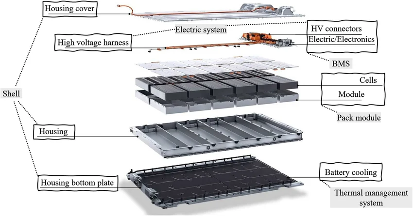
Introduction
Electric vehicles rely heavily on lithium-ion battery packs composed of numerous cells connected in series to achieve high voltage levels required for propulsion. Over time, these cells experience imbalances in state of charge due to variations in capacity, internal resistance, and self-discharge rates. Battery management system PCBs play a critical role in monitoring and correcting these imbalances through cell balancing techniques. Effective balancing extends battery life, maximizes usable capacity, and enhances safety by preventing overvoltage or undervoltage conditions. This article examines advanced cell balancing methods implemented on EV battery management PCBs, focusing on passive and active approaches including switched capacitor balancing and resonant balancing. A comparative analysis of balancing efficiency, balancing speed, and cost analysis will guide engineers in selecting optimal solutions for high-reliability applications.
Cell balancing circuits integrated into BMS PCBs must withstand harsh automotive environments, including temperature extremes and vibration. Design choices impact overall system performance, thermal management, and PCB layout complexity. Engineers prioritize techniques that align with power density requirements while minimizing losses. Understanding the trade-offs between simplicity and performance is essential for robust EV designs. This analysis draws on established engineering principles to provide actionable insights.
The Importance of Cell Balancing in EV Battery Management Systems
Imbalanced cells in EV battery packs lead to reduced overall capacity as the pack is limited by the weakest cell during charge and discharge cycles. Without balancing, stronger cells remain underutilized, accelerating degradation and potentially triggering thermal runaway risks. BMS PCBs incorporate balancing circuitry to equalize cell voltages, ensuring uniform state of charge across the pack. This process directly influences range, charging time, and longevity, critical metrics for EV competitiveness. Industry demands for faster charging and higher energy density amplify the need for efficient balancing on compact PCBs.
Regulatory and performance standards underscore the necessity of reliable BMS designs. For instance, adherence to IPC-6012E ensures PCB qualification for rigid boards in demanding applications, supporting consistent electrical performance. Balancing techniques must integrate seamlessly with monitoring ICs, current sensors, and protection FETs on the same PCB. Poor balancing efficiency results in excess heat generation, complicating thermal dissipation in space-constrained modules. Engineers must evaluate techniques based on pack size, cell count, and operational profiles to optimize system-level outcomes.
Fundamentals of Cell Balancing Techniques
Cell balancing operates by redistributing charge among cells to align their voltages or states of charge. Passive cell balancing dissipates excess energy from higher-voltage cells as heat using resistors, a straightforward method suitable for low-power applications. Active cell balancing transfers energy between cells, preserving overall pack energy and improving efficiency. Subtypes of active balancing include switched capacitor balancing, which shuttles charge via capacitors, and resonant balancing, employing inductive elements for near-lossless transfer. Each method imposes unique demands on PCB routing, component selection, and control algorithms.
The choice of technique affects BMS PCB architecture profoundly. Passive methods require minimal components but generate waste heat, necessitating robust thermal vias and copper pours. Active methods demand precise gate drivers, high-frequency switches, and isolation for safety. Balancing speed determines how quickly imbalances are corrected, crucial during fast charging scenarios. Balancing efficiency dictates energy recovery rates, impacting vehicle range. Cost analysis weighs component count, PCB layers, and assembly complexity against performance gains.
Passive Cell Balancing on BMS PCBs
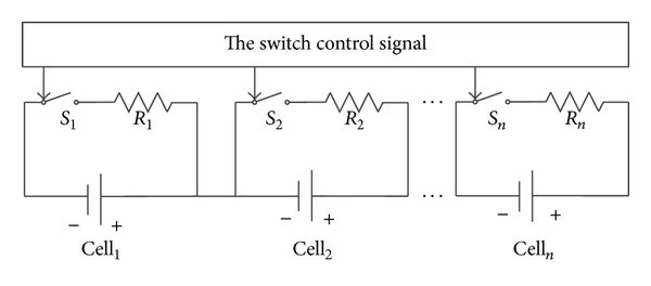
Passive cell balancing employs bleed resistors connected across each cell via MOSFET switches controlled by the BMS microcontroller. When a cell exceeds the target voltage, the switch activates, shunting current through the resistor until equilibrium. This method excels in simplicity, requiring few components and low control overhead. However, it wastes energy as heat, limiting balancing efficiency to below 100 percent since no charge is recycled. On PCBs, resistors must handle continuous dissipation, often rated for automotive temperatures per JEDEC guidelines.
Implementation involves careful resistor selection for power rating and tolerance, with PCB traces sized to minimize voltage drops. Thermal management is key, as heat from multiple bleed resistors can elevate local temperatures, risking delamination. Engineers position resistors near board edges for airflow or add heatsinks in high-power packs. While cost-effective for small imbalances, passive cell balancing struggles with large voltage spreads due to slow balancing speed. It suits cost-sensitive designs where energy loss is acceptable during extended charging periods.
Active Cell Balancing Techniques
Active cell balancing enhances performance by shuttling energy from overcharged to undercharged cells, achieving higher balancing efficiency. These circuits use power electronics to enable bidirectional energy flow, controlled by voltage monitoring and algorithms. Common implementations on BMS PCBs include switched capacitor and resonant methods, each optimized for specific pack configurations. Active approaches demand multilayer PCBs for signal integrity and power delivery, with gate drive circuits isolated to prevent noise coupling. Balancing speed improves significantly, allowing rapid correction during dynamic EV operation.
Switched Capacitor Balancing
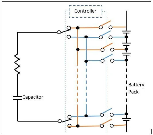
Switched capacitor balancing employs capacitors switched between cells to transfer discrete charge packets. MOSFETs connect the capacitor alternately to source and sink cells, with switching frequency dictating transfer rate. This method offers moderate balancing efficiency, typically recovering 80 to 90 percent of shuttled energy, though losses occur in switches and ESR. PCB design requires low-ESR capacitors and short, wide traces to reduce inductance and resistance. Double-tiered topologies accelerate balancing speed by paralleling multiple capacitors.
Control logic monitors cell voltages and prioritizes transfers, often using flyback or chain configurations for scalability. Complexity arises from synchronization to avoid shoot-through currents, necessitating dead-time management. Cost analysis reveals higher upfront expenses due to capacitor banks and drivers, but long-term savings from preserved energy. Suitable for mid-range EV packs with 10 to 20 cells in series.
Resonant Balancing
Resonant balancing leverages inductor-capacitor tanks to resonate at high frequencies, enabling efficient charge transfer via quasi-resonant switching. Energy oscillates between cells through a shared inductor, minimizing losses with zero-voltage switching. This yields superior balancing efficiency approaching 95 percent and the fastest balancing speed among active methods, ideal for large packs. PCB challenges include managing high di/dt currents, requiring thick copper layers and via stitching for low impedance paths.
Transformers or multi-winding inductors facilitate pack-wide balancing, reducing component count for scalability. Control involves phase-locked loops or adaptive frequency tuning for optimal resonance. While offering premium performance, resonant methods incur higher costs from magnetics and precise components. They excel in high-voltage packs where speed outweighs expense.
Comparative Analysis of Cell Balancing Techniques
Engineers compare techniques across key metrics to inform BMS PCB designs. Passive cell balancing leads in cost analysis with minimal components and simple assembly, but lags in balancing efficiency and balancing speed due to thermal dissipation. Active methods reverse this, with switched capacitor balancing striking a balance: moderate cost, improved efficiency over passive, and acceptable speed for most EVs. Resonant balancing tops charts in efficiency and speed but demands premium investment.
- Passive Cell Balancing — Balancing Efficiency: Low (dissipative); Balancing Speed: Slow; Cost Analysis: Low; PCB Complexity: Low
- Switched Capacitor — Balancing Efficiency: Medium-High; Balancing Speed: Medium; Cost Analysis: Medium; PCB Complexity: Medium
- Resonant Balancing — Balancing Efficiency: High; Balancing Speed: Fast; Cost Analysis: High; PCB Complexity: High
Hybrid approaches combine passive for coarse balancing and active for fine-tuning, optimizing overall performance.
PCB Design Considerations and Best Practices
BMS PCBs hosting balancing circuits require high-reliability features per IPC-A-610 standards for acceptability criteria. Multilayer stacks isolate power and signal planes, with embedded capacitors reducing loop areas. Component placement prioritizes thermal symmetry, avoiding hotspots near inductors or resistors. High-current paths use 2-oz copper or bus bars, while vias support current sharing.
Best practices include simulation of EMI from switching nodes, using ground planes for shielding. Firmware algorithms adapt balancing current based on temperature and SOC, preventing overstress. Qualification testing verifies performance under vibration and thermal cycling. For active circuits, galvanic isolation protects low-voltage logic from high-voltage domains. Adopting J-STD-001 guidelines ensures soldering quality for long-term reliability.
Conclusion
Advanced cell balancing techniques on EV battery management PCBs are pivotal for optimizing lithium-ion pack performance. Passive cell balancing offers simplicity and low cost, while active methods like switched capacitor and resonant balancing deliver superior efficiency and speed at increased complexity. Comparative analysis reveals resonant as ideal for premium applications, with switched capacitor suiting balanced needs. PCB engineers must integrate these with reliability standards to meet automotive demands. Selecting the right method enhances range, safety, and lifespan, driving EV adoption forward.
FAQs
Q1: What is the main difference between active cell balancing and passive cell balancing on BMS PCBs?
A1: Active cell balancing transfers energy between cells, achieving higher balancing efficiency by recycling charge, whereas passive cell balancing dissipates excess energy as heat via resistors. Active methods support faster balancing speed, crucial for large EV packs, but require more complex PCB routing and components. Passive suits low-cost designs with minor imbalances. Overall, active enhances energy utilization in demanding applications.
Q2: How does switched capacitor balancing improve balancing speed compared to passive methods?
A2: Switched capacitor balancing shuttles charge via capacitors between cells, enabling quicker equalization than passive resistor bleeding. Multiple capacitors in parallel or tiered setups accelerate the process, reducing time for voltage convergence. On BMS PCBs, optimized switching frequencies minimize losses. This makes it viable for mid-sized packs where speed matters without resonant complexity.
Q3: Why is balancing efficiency critical in resonant balancing for EVs?
A3: Resonant balancing uses inductive resonance for near-lossless energy transfer, maximizing balancing efficiency and preserving pack capacity. This minimizes heat and extends range in high-power EVs. Cost analysis shows higher initial investment offset by operational gains. PCB designs must handle high frequencies for peak performance.
Q4: What factors influence cost analysis in cell balancing PCB implementations?
A4: Cost analysis considers component count, PCB layers, and assembly per standards like IPC-6012E. Passive is cheapest due to simplicity, while resonant demands magnetics and drivers. Balancing efficiency and speed trade-offs guide selection for pack size and budget. Engineers balance upfront costs with lifecycle savings from reduced energy loss.
References
IPC-6012E — Qualification and Performance Specification for Rigid Printed Boards. IPC, 2015
IPC-A-610H — Acceptability of Electronic Assemblies. IPC, 2019
J-STD-001H — Requirements for Soldered Electrical and Electronic Assemblies. IPC, 2018


