Introduction
Wind turbine control printed circuit boards (PCBs) manage critical functions such as power conversion, sensor monitoring, and fault detection in demanding offshore and onshore environments. These PCBs face constant exposure to vibration, thermal cycling, humidity, and potential salt corrosion, which demand assembly processes that exceed standard consumer electronics practices. Surface mount technology (SMT) assembly for wind turbine PCBs has evolved to incorporate advanced techniques ensuring long-term reliability and minimal downtime. High-reliability SMT addresses the high density of components required for compact control modules while mitigating risks like solder joint fatigue. This article explores key methods including BGA assembly, conformal coating, and selective wave soldering, providing engineers with practical insights for robust implementations.
Why High-Reliability SMT Matters for Wind Turbine Control PCBs
High-reliability SMT refers to assembly processes optimized for mission-critical applications where failure can lead to turbine shutdowns and substantial revenue losses. In wind turbines, control PCBs operate under continuous mechanical stress and environmental extremes, necessitating solder joints and protections that withstand millions of cycles. Standard SMT might suffice for benign environments, but wind turbine applications require Class 3 assembly criteria as defined in IPC-A-610 to ensure defect-free performance. This level emphasizes zero tolerance for voids, cracks, or misalignments that could propagate under vibration. Moreover, the integration of fine-pitch components like BGAs demands precision to prevent issues such as head-in-pillow defects, which compromise signal integrity in high-speed control circuits. Ultimately, adopting high-reliability SMT extends PCB lifespan, reduces maintenance costs, and supports the industry's push for 20+ year operational reliability.
Fundamental Principles of SMT Assembly in Harsh Environments
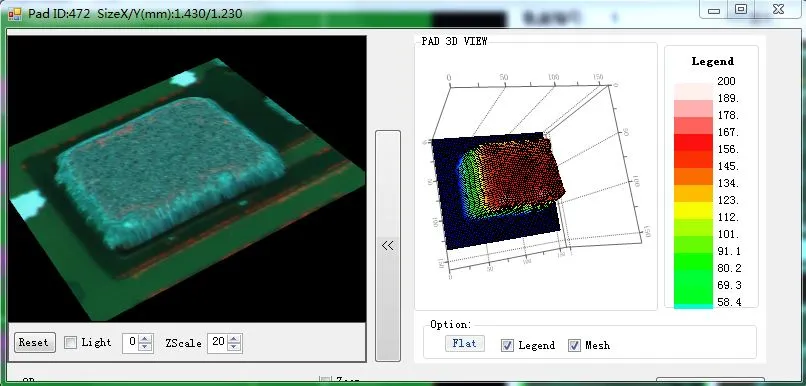
SMT assembly begins with solder paste printing through laser-cut stencils, where uniform deposition is critical to avoid bridging or insufficient volume on pads. For wind turbine PCBs, paste rheology must accommodate high-vibration resistance, often using low-residue formulations that minimize cleaning needs post-reflow. Placement accuracy, typically under 50 microns for 0.4mm pitch devices, relies on vision-guided robots to handle warped boards common in thick copper designs. Reflow soldering follows a profile with precise ramp-up, soak, and peak temperatures to achieve full melt without overheating components. In high-reliability SMT, nitrogen atmospheres prevent oxidation, ensuring shiny, concave fillets indicative of proper wetting. These principles form the backbone for techniques like BGA assembly, where hidden joints require X-ray verification for voiding below 25% per ball.
Advanced BGA Assembly Techniques for Wind Turbine PCBs
Ball Grid Array (BGA) components dominate wind turbine control PCBs due to their high I/O density for processors and FPGAs handling real-time data. BGA assembly challenges stem from thermal expansion mismatches between silicon dies, substrates, and PCB laminates, potentially causing warpage during reflow. Engineers mitigate this by selecting low-CTE materials and implementing multi-zone reflow ovens with linear ramp rates below 2°C/second. Post-reflow, automated X-ray systems detect non-wet opens or bridging, while shear testing validates joint strength per J-STD-001 guidelines. For enhanced reliability, underfill epoxies fill gaps under large BGAs, distributing stress evenly during vibration. Troubleshooting BGA failures often involves acoustic microscopy to identify delaminations early, allowing process tweaks like extended pre-bake for moisture-sensitive devices.
Conformal Coating Applications in High-Reliability SMT
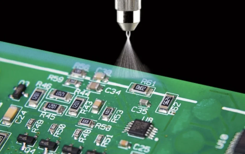
Conformal coating provides a dielectric barrier against moisture ingress and ionic contamination on assembled wind turbine PCBs. Applied post-cleaning via selective spraying or dipping, it encapsulates SMT components without bridging high-voltage gaps. Materials like urethane or parylene offer flexibility to accommodate thermal expansion, with thickness controlled to 25-75 microns for optimal protection. Cure processes, whether UV or thermal, must avoid bubbles that trap contaminants, as inspected under IPC-A-610 criteria for coverage uniformity. In humid coastal installations, acrylic coatings excel in salt resistance, while silicone variants handle extreme temperature swings. Common troubleshooting includes edge coverage verification and fluorescence testing to spot thin spots prone to arcing.
Integrating Wave Soldering in Mixed-Technology Wind Turbine Assemblies
While predominantly SMT, wind turbine control PCBs often include through-hole (THT) connectors and relays, making wave soldering essential for mixed assemblies. Wave soldering for wind turbine applications uses a finger-type pallet to expose only THT areas, preventing SMT rework from flux residue. Flux application must be low-solids to minimize post-clean demands, with preheat zones stabilizing boards against thermal shock. The solder wave, typically eutectic SnPb or lead-free SAC305, achieves dross-free joints via turbulent laminar flow. High-reliability requires drag soldering for dual-sided boards, inspected for icicles or fills exceeding 75%. Process controls like nitrogen blanketing reduce oxidation, aligning with J-STD-001 for dedicated service electronics.
Best Practices and Troubleshooting for Optimal SMT Reliability
Implement automated optical inspection (AOI) immediately post-placement and post-reflow to catch misalignments or paste shifts early in the SMT line. For BGA-heavy boards, integrate 3D X-ray for void analysis, targeting under 10% average to enhance fatigue life under vibration. Board support fixtures during reflow counteract warpage, especially for rigid-flex hybrids in turbine nacelles. Conformal coating thickness mapping via laser profilometry ensures compliance, preventing hotspots. Troubleshooting tombstoning involves paste volume optimization and symmetric heating; bridging resolves with stencil aperture reduction and shear thinning pastes. Vibration qualification testing simulates operational profiles, iterating assembly until pass rates exceed 99.9%.
- Common SMT Defect: Solder Beading; Root Cause: Excessive paste volume; Troubleshooting Fix: Reduce stencil thickness, optimize squeegee pressure.
- Common SMT Defect: Head-in-Pillow (BGA); Root Cause: Reflow profile mismatch; Troubleshooting Fix: Adjust peak temp, extend time above liquidus.
- Common SMT Defect: Coating Voids; Root Cause: Trapped air in spray; Troubleshooting Fix: Vacuum degas material, use dip method.
- Common SMT Defect: Wave Solder Bridging; Root Cause: Flux over-application; Troubleshooting Fix: Nozzle calibration, post-wave hot air leveling.
Regular process audits per IPC standards maintain capability indices above 1.33, crucial for wind turbine supply chains.
Conclusion
Advanced SMT assembly techniques like precise BGA handling, robust conformal coating, and controlled wave soldering elevate wind turbine control PCBs to meet extreme reliability demands. By adhering to high-reliability practices, engineers minimize field failures and maximize turbine uptime. Key to success lies in integrating inspection, material selection, and process controls tailored to environmental stresses. These methods not only ensure compliance with industry benchmarks but also future-proof designs for larger offshore installations. Implementing them systematically transforms potential vulnerabilities into strengths for enduring performance.
FAQs
Q1: What distinguishes high-reliability SMT for wind turbine PCBs from standard assembly?
A1: High-reliability SMT for wind turbine PCBs emphasizes Class 3 criteria with enhanced inspections like X-ray for BGA assembly and nitrogen reflow to combat vibration and corrosion. Processes include precise stencil printing and conformal coating to seal against humidity. This approach prevents defects like microcracks that standard methods overlook, ensuring 20+ year lifecycles in harsh conditions. Troubleshooting focuses on root causes such as warpage mitigation.
Q2: How does BGA assembly impact reliability in wind turbine control systems?
A2: BGA assembly provides dense interconnects vital for control processors but requires X-ray void detection and underfill to resist thermal cycling fatigue. Alignment tolerances under 0.1mm prevent opens during vibration. Per J-STD-001, joint integrity testing validates performance. Engineers troubleshoot head-in-pillow by refining reflow profiles, boosting overall PCB robustness.
Q3: Why apply conformal coating in SMT assembly for wind turbine PCBs?
A3: Conformal coating shields SMT joints from moisture and salt in offshore environments, extending reliability. Selective application avoids component overheating, with IPC-A-610 guiding uniformity. It prevents dendritic growth under bias. Common issues like pinholes resolve via material viscosity adjustments, maintaining insulation resistance.
Q4: When is wave soldering used in wind turbine PCB manufacturing?
A4: Wave soldering suits mixed SMT-THT assemblies with connectors in wind turbine controls, using pallets for selective exposure. It ensures robust THT joints resistant to mechanical stress. Flux management per J-STD-001 minimizes residue. Troubleshooting bridging involves preheat optimization for lead-free alloys.
References
IPC-A-610J — Acceptability of Electronic Assemblies. IPC, 2020
J-STD-001H — Requirements for Soldered Electrical and Electronic Assemblies. IPC, 2020
IPC-6012DS — Qualification and Performance Specification for Rigid Printed Boards. IPC, 2015
IPC-CC-830C — Qualification and Performance of Electrical Insulating Compounds for Conformal Coatings. IPC, 2019


