Introduction
Flexible printed circuit boards, often called flex PCBs, open up exciting possibilities for electronic hobbyists working on compact and innovative projects. Unlike traditional rigid boards, these circuits can bend and twist to fit into tight spaces, making them ideal for wearables, drones, and custom sensors. As hobbyists dive into more advanced builds, understanding flexible PCB basics becomes essential for achieving reliable performance without bulky wiring. This guide covers what a flexible PCB is, its key advantages, and practical steps to incorporate them into your projects. By following factory-driven insights aligned with industry standards, you can avoid common pitfalls and create durable designs. Whether prototyping a flexible LED display or a bendable robot arm, flex PCBs offer the freedom to experiment creatively.
What Is a Flexible PCB?
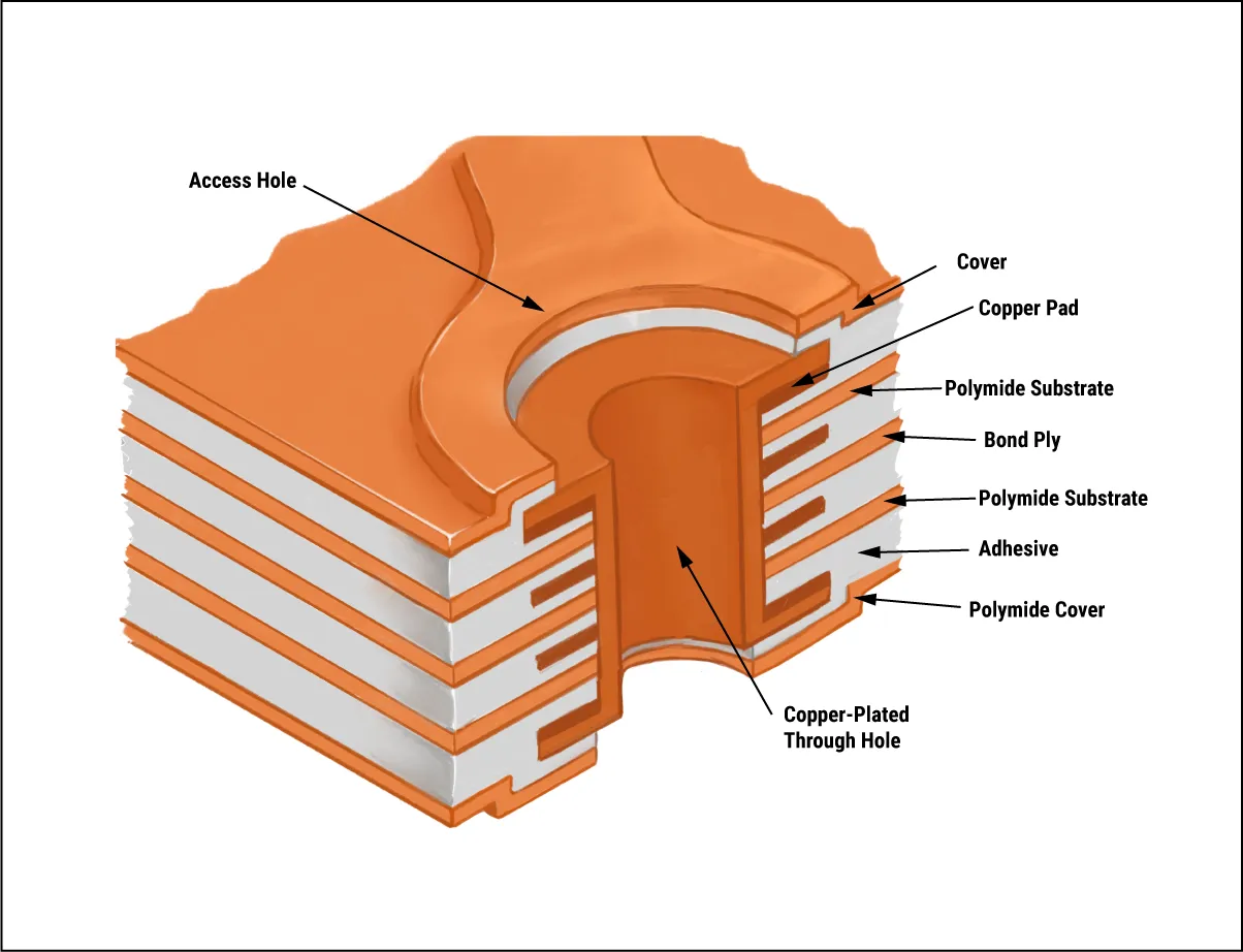
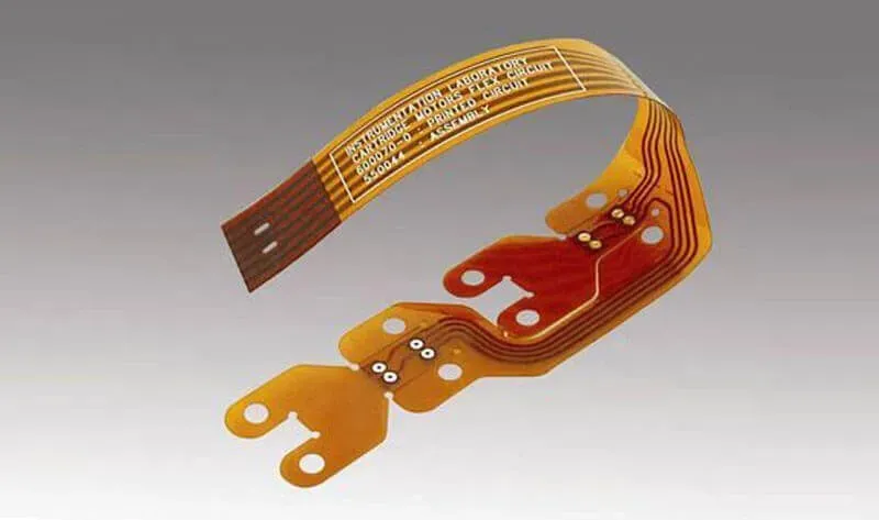
A flexible PCB is a type of printed circuit board constructed with a bendable substrate material instead of rigid fiberglass, allowing it to conform to curved surfaces or dynamic movements. The core substrate typically uses polyimide film, which provides the necessary flexibility while maintaining electrical insulation and thermal stability. Conductive copper traces are laminated onto this substrate, often protected by a coverlay similar to solder mask on rigid boards. Flex PCBs come in various configurations, including single-sided for simple connections, double-sided for more complex routing, multilayer for higher density, and rigid-flex hybrids that combine stiff sections with flexible areas. These boards replace traditional wire harnesses, reducing assembly time and potential failure points in electronic projects. For hobbyists, grasping what a flexible PCB is means recognizing its role in enabling slim, lightweight designs that rigid boards simply cannot match.
Flexible PCB Basics: Materials and Construction
Flexible PCB basics revolve around selecting materials that balance flexibility, durability, and conductivity. Polyimide serves as the primary substrate due to its excellent resistance to heat and chemicals, commonly available in thicknesses that support repeated bending. Copper foil, often rolled annealed type for better flex endurance, forms the conductive paths, with thicknesses chosen based on current requirements. A coverlay protects the traces, while adhesives bond layers in multilayer designs. Construction begins with laminating copper to the substrate, followed by imaging, etching, and applying the coverlay, much like rigid PCB processes but optimized for flexibility. Adhering to standards like IPC-6013 ensures the final board meets performance criteria for qualification and reliability.
In single-sided flex PCBs, traces run on one side only, ideal for basic hobbyist interconnects like sensor strips. Double-sided versions add traces on both sides with plated through-holes for interlayer connections, suitable for moderately complex circuits. Multilayer flex PCBs stack multiple layers for signal integrity in denser layouts, while rigid-flex integrates rigid FR4 sections for component mounting. Each type influences manufacturing yield and cost, so hobbyists should start with simpler single or double-sided for initial projects. Factory practices emphasize precise layer alignment to prevent delamination during flexing.
Flexible PCB Advantages for Electronic Projects
Flexible PCB advantages make them a game-changer for hobbyists tackling space-constrained builds. Their lightweight nature reduces overall project weight, crucial for drones or portable gadgets where every gram counts. By eliminating bulky connectors and cables, flex PCBs streamline assembly and minimize points of failure from vibration or movement. They enable three-dimensional packaging, folding circuits to fit irregular shapes like curved enclosures or wearable bands. Enhanced reliability comes from fewer interconnections, resisting fatigue in dynamic applications. For electronic projects, these benefits translate to sleeker prototypes that perform reliably under real-world stresses.
Another key advantage lies in thermal management, as flex materials handle wider temperature ranges without warping. They support high-density routing in compact areas, freeing up space for batteries or sensors. Cost savings emerge in high-volume hobbyist runs by reducing wiring labor, though initial design effort is higher. Vibration resistance suits robotics or automotive-inspired projects, where rigid boards might crack. Overall, flexible PCB advantages empower hobbyists to push creative boundaries while maintaining functionality.

Flexible PCB Tutorial: Designing Your First Flex Board
This flexible PCB tutorial walks hobbyists through the essentials of designing a basic single-sided flex circuit for a project like a bendable LED strip. Start by sketching the layout, identifying static and dynamic bend zones to guide material choices. Use design software to define the stackup: select polyimide substrate, copper weight around 1 oz for low-power hobby circuits, and add coverlay over traces. Route traces with generous widths in flex areas, at least twice that of rigid sections, and avoid sharp bends or vias in dynamic regions. Incorporate strain relief features like teardrops at pads and curved trace paths. Export Gerber files specifying flex layers and send for fabrication, requesting IPC-2223 compliant design rules for bend radius and plating.
Next, plan component placement on stiffener areas if needed, using polyimide or FR4 reinforcements for soldering stability. Simulate flexing mentally: ensure minimum bend radius exceeds ten times the board thickness to prevent cracking. Test prototypes by hand-bending and checking continuity with a multimeter. For assembly, use low-temperature solder to avoid damaging the substrate. Common tools include fine-tip irons and flux suited for polyimide. This step-by-step flexible PCB tutorial builds confidence for iterating on projects like flexible displays or jointed robot links.
Best Practices and Troubleshooting for Flex PCBs
Follow best practices to maximize flex PCB reliability in hobbyist projects. Design traces perpendicular to bend lines in static areas but parallel in dynamic ones to distribute stress evenly. Limit layer count to two or four for cost-effective prototypes, escalating to multilayer only for signal-heavy designs. Apply stiffeners under connectors or ICs to prevent tearing during handling. During testing, perform cyclic bends per factory protocols to verify endurance before full deployment. Address issues like coverlay bubbles by ensuring clean lamination, and delamination through proper adhesive selection.
Troubleshooting starts with visual inspection for cracks post-flexing, using magnification to spot trace fractures. Continuity failures often stem from overly tight bends; redesign with larger radii. Solder joint issues arise from heat sensitivity, so profile reflow carefully. For impedance mismatches in faster signals, reference IPC-6013 for controlled stackups. Document iterations to refine future boards. These practices ensure hobby projects transition smoothly from prototype to functional builds.
Applications in Hobbyist Electronic Projects
Hobbyists leverage flex PCBs in flexible PCB application scenarios such as wearables for skin-conforming sensors that track motion without rigid bulk. In drones, they route signals through folding arms, saving weight for longer flights. Custom keyboards or game controllers benefit from ergonomic curves enabled by flex designs. Robotic joints use rigid-flex for hinged connections combining strength and flexibility. Camera modules in DIY gimbals fold compactly during storage. These flexible PCB application examples highlight how flexible PCB basics enhance project versatility.
Conclusion
Mastering flexible PCBs equips hobbyists with tools for innovative, compact electronics. From understanding what a flexible PCB is to applying advantages in real projects, this guide provides a solid foundation. Key flexible PCB basics like materials and construction ensure reliable outcomes when following standards. The tutorial and best practices empower hands-on experimentation without common errors. As you prototype, prioritize bend-aware designs for durability. Embrace flex technology to elevate your electronic projects to new levels of creativity and performance.
FAQs
Q1: What is a flexible PCB and how does it differ from rigid PCBs?
A1: A flexible PCB uses a bendable polyimide substrate with copper traces, allowing it to flex and conform to shapes unlike rigid FR4 boards. This makes flexible PCB basics ideal for space-limited hobby projects. Rigid boards suit static mounts, while flex handles dynamic movement. Differences include lighter weight and no need for connectors. Always design per standards for best results.
Q2: What are the main flexible PCB advantages for electronic hobbyists?
A2: Flexible PCB advantages include reduced weight, space savings, and vibration resistance, perfect for wearables or drones. They eliminate wiring harnesses, simplifying assembly. Enhanced reliability comes from integrated connections. Hobbyists gain design freedom for curved enclosures. Drawbacks like higher cost apply to complex layers, but basics suit simple projects well.
Q3: How can beginners follow a flexible PCB tutorial for their first project?
A3: In a flexible PCB tutorial, start with single-sided design, mark bend zones, and use wide traces. Select polyimide substrate and export Gerbers with stackup notes. Prototype small, test bends, and add stiffeners for components. Avoid vias in flex areas. This approach builds skills for hobby sensors or lights reliably.
Q4: What standards should hobbyists know for flexible PCB basics?
A4: Know IPC-6013 for qualification and performance of flexible printed boards, ensuring factory-quality output. IPC-2223 guides design for flex and rigid-flex, covering bend radii and layouts. These standards prevent failures in hobby projects. Reference them during fabrication specs. No other metrics needed for starters.
References
- IPC-6013E — Qualification and Performance Specification for Flexible Printed Boards. IPC
- IPC-2223E — Sectional Design Standard for Flexible/Rigid-Flexible Printed Boards. IPC


