Introduction
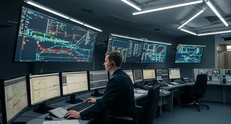
Railway control centers serve as the central nervous system for managing vast networks of tracks, signals, and trains across railway infrastructure. These facilities rely on sophisticated electronic systems to monitor train positions, process signals, and coordinate responses in real time. At the heart of these systems are control center PCBs, which provide the interconnectivity and processing power needed for reliable operation. Printed circuit boards in these environments must withstand continuous use while supporting monitoring systems and communication systems essential for safety. Engineers designing for such applications focus on durability to prevent disruptions that could lead to delays or hazards. This article explores the critical role of control center PCBs in maintaining seamless railway operations.
Understanding Control Center PCBs in Railway Infrastructure
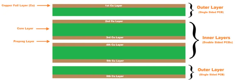
Control center PCBs are specialized printed circuit boards that integrate processors, memory, interfaces, and power regulation circuits tailored for railway control environments. Incorporating railway signaling PCB design standards is critical to ensure safety, interoperability, and long-term reliability in mission-critical transportation infrastructure. These boards connect sensors from tracks and trains to central displays and decision-making software, forming the backbone of railway infrastructure management. Unlike standard consumer PCBs, control center PCBs prioritize long-term reliability under demanding conditions such as constant vibration from nearby operations and fluctuating temperatures in control rooms. They handle data from multiple sources, ensuring that operators receive accurate updates on train movements and track statuses. The design incorporates multilayer constructions to manage signal integrity over high-speed data links. Overall, these PCBs enable the coordination that keeps millions of passengers moving safely each day.
In railway infrastructure, control center PCBs interface with field equipment like trackside signals and axle counters, processing inputs to generate control outputs. This integration demands precise routing to minimize electromagnetic interference, which could corrupt critical data. Engineers select materials with high glass transition temperatures to resist thermal cycling from heating and cooling systems in control centers. Conformal coatings protect against dust and humidity common in industrial settings. Such features ensure that the PCBs contribute to the uptime required for 24/7 railway operations.
Key Technical Principles Behind Control Center PCBs
The engineering of control center PCBs begins with understanding the environmental stresses inherent to railway infrastructure. Vibration and mechanical shock from train passages transmit through building structures, requiring boards with reinforced mounting points and flexible traces to avoid fatigue cracks. Thermal management is crucial, as control rooms can experience wide temperature swings; heat sinks and thermal vias dissipate power from processors handling real-time analytics. Signal integrity principles guide trace impedance control, especially for high-frequency signals in monitoring systems. Power integrity ensures stable voltage rails for analog-to-digital converters processing sensor data. These principles collectively prevent failures that could cascade into system-wide issues.
Multilayer PCB stacks allow separation of power, ground, and signal planes, reducing crosstalk in dense layouts typical of control centers. Controlled impedance traces maintain data rates for Ethernet links connecting to remote substations. Vias are designed with stitching for low inductance returns, supporting fast edge rates in communication protocols. Material selection focuses on low coefficient of thermal expansion to match component leads, minimizing solder joint stress during operation. Fabrication follows strict tolerances to achieve these performance levels without compromising yield.
PCBs in Monitoring Systems for Railway Control
Monitoring systems in railway control centers depend on PCBs to aggregate data from distributed sensors across the network. These boards host microcontrollers that poll inputs from track circuits, detecting train occupancy and speed via inductive loops embedded in rails. Digital signal processors on the PCBs filter noise from environmental interference, ensuring accurate position reporting. Environmental sensors for temperature, humidity, and wind feed into PCBs that run predictive algorithms for maintenance alerts. Integration with displays allows operators to visualize network status on large screens driven by graphics controllers on dedicated PCBs. This setup enables proactive responses to potential issues before they escalate.
PCBs in monitoring systems often include analog front-ends with high-resolution ADCs to handle varying signal amplitudes from distant field devices. Isolation barriers protect against ground loops induced by long cable runs. Firmware on embedded processors executes fault detection routines, logging events for post-analysis. Redundant power supplies on the boards ensure continuity during utility fluctuations common in remote control centers. Such designs uphold the precision needed for safe train spacing and routing decisions.
Role of PCBs in Communication Systems
Communication systems linking control centers to trains and wayside equipment rely on PCBs optimized for robust data transmission. These boards integrate transceivers for protocols like GSM-R or radio-based systems, handling voice and data packets simultaneously. Antennas connect via RF sections on the PCBs, with baluns matching impedance for efficient signal propagation. Processors manage encryption and prioritization, ensuring safety-critical messages like emergency stops take precedence. Fiber optic interfaces on high-density interconnect PCBs support backbone links to regional substations. This infrastructure facilitates real-time coordination across hundreds of kilometers of railway infrastructure.
In control centers, communication PCBs route traffic through switches and routers mounted on modular boards for scalability. Electromagnetic compatibility design suppresses emissions that could interfere with nearby signaling equipment. Error-correcting codes implemented in hardware detect and retransmit corrupted packets. Backup channels on redundant PCBs provide failover for uninterrupted service. These features make communication systems resilient, supporting the seamless flow of operational commands.
Safety-Critical Design in Control Center PCBs
Safety-critical design elevates control center PCBs to a level where failure modes are systematically mitigated. Adherence to IEC 61508 ensures functional safety through hazard analysis and risk reduction via redundancy and diagnostics. Dual-channel architectures compare outputs from independent processors, voting to confirm decisions before actuation. Watchdog timers reset errant microcontrollers, preventing hangs in monitoring loops. Trace widths are oversized for current carrying to avoid hotspots that could lead to intermittent faults. Component selection favors those qualified for extended temperature ranges and vibration profiles.
Fail-safe principles guide PCB layout, with segregated safety partitions isolating critical paths from general computing. Incorporating implementing functional safety in railway signaling PCBs is essential to ensure deterministic behavior, fault tolerance, and predictable degradation modes in safety-critical transportation systems. Self-testing routines at power-up verify memory and connectivity before enabling outputs. Conformal coatings and potting enhance mechanical integrity against shock. IEC 61508-compliant verification includes environmental stress screening like thermal cycling and random vibration. IPC-6012 specifications govern qualification, ensuring boards meet performance under qualification and performance criteria for rigid printed boards. These measures collectively safeguard lives by making system failures improbable.
Best Practices for Implementing Control Center PCBs
Engineers follow best practices in material selection, starting with laminates offering high Tg for thermal stability in railway environments. Heavy copper layers handle power demands from drives and relays without excessive voltage drop. Surface finishes like ENIG provide reliable solder joints for fine-pitch components in dense monitoring boards. Manufacturing incorporates automated optical inspection to catch defects early. Assembly uses no-clean fluxes to minimize residues that could cause dendrite growth over time.
Testing regimes simulate operational stresses, including accelerated life tests per IPC guidelines. Vibration profiles mimic track-induced shakes, while humidity chambers assess coating efficacy. Functional tests validate communication throughput under load. Documentation traces every design choice to requirements, aiding certification. Modular designs allow field upgrades without full system downtime. These practices ensure control center PCBs deliver decades of service.
Common Challenges and Troubleshooting Approaches
Challenges in control center PCBs often stem from thermal expansion mismatches leading to via cracks after years of cycling. Troubleshooting involves X-ray inspection and thermal imaging to pinpoint hotspots. Signal crosstalk in high-speed communication sections manifests as bit errors; solutions include guard traces and stitching vias. Power supply ripple affects ADC accuracy in monitoring systems, addressed by adding decoupling capacitors near pins. Mechanical fatigue from mounts loosening requires torque verification during maintenance. Proactive logging from onboard diagnostics aids root cause analysis, preventing recurrence.
Environmental ingress through imperfect seals causes corrosion; regular conformal coating integrity checks mitigate this. Firmware bugs in safety logic demand rigorous simulation before deployment. Collaboration between design and field teams refines layouts based on operational data. These troubleshooting steps maintain system integrity without overhauls.
Conclusion
Control center PCBs are indispensable for the reliability of railway infrastructure, powering monitoring systems and communication systems with unwavering precision. Their safety-critical design, guided by standards like IEC 61508 and IPC-6012, addresses the unique demands of continuous operation. Engineers achieve this through meticulous material choices, robust layouts, and rigorous testing. As railways evolve toward automation, these boards will integrate more AI-driven analytics while upholding safety. Ultimately, well-engineered control center PCBs ensure seamless operations, protecting passengers and optimizing efficiency across global networks.
FAQs
Q1: What makes control center PCBs different from standard PCBs in railway infrastructure?
A1: Control center PCBs feature multilayer stacks and high-Tg materials to handle vibration, thermal cycling, and high-reliability needs in monitoring systems. They incorporate redundancy for safety-critical design, unlike general-purpose boards. Testing exceeds typical levels to simulate decades of use. This ensures uninterrupted data processing for train control.
Q2: How do PCBs support safety-critical design in railway communication systems?
A2: PCBs in communication systems use dual processors and error detection per IEC 61508 to verify message integrity before relay. Isolation and EMC shielding prevent interference with signaling. Redundant paths provide failover. These elements minimize risks in real-time train-to-center links.
Q3: What are common best practices for manufacturing control center PCBs?
A3: Select laminates meeting IPC-6012 for performance qualification. Apply conformal coatings for environmental protection. Perform vibration and thermal shock tests. Ensure precise drilling and plating for via reliability. Document processes for traceability in railway applications.
Q4: Why is thermal management vital for PCBs in railway monitoring systems?
A4: Monitoring systems process sensor data continuously, generating heat from processors and converters. Effective vias and heat sinks prevent performance degradation. This maintains accuracy in track occupancy detection. Poor management leads to false alarms or missed faults.
References
IEC 61508 - Functional safety of electrical/electronic/programmable electronic safety-related systems. IEC, 2010
IPC-6012E - Qualification and Performance Specification for Rigid Printed Boards. IPC, 2015
IPC-A-610G - Acceptability of Electronic Assemblies. IPC, 2017


