Introduction
Flexible printed circuit boards, or flex PCBs, enable compact designs in applications ranging from consumer electronics to aerospace systems. These boards excel in dynamic environments where bending and folding are necessary, but their inherent thinness poses challenges like mechanical stress and insufficient support for components. Flexible PCB stiffeners address these issues by adding localized rigidity without compromising overall flexibility. Engineers rely on them to improve assembly yields, prevent solder joint failures, and extend service life in vibrating or high-cycle bend scenarios. This article explores flexible PCB stiffener materials, placement strategies, design principles, and their role in component support, drawing on established engineering practices.
What Are Flexible PCB Stiffeners and Why Do They Matter?
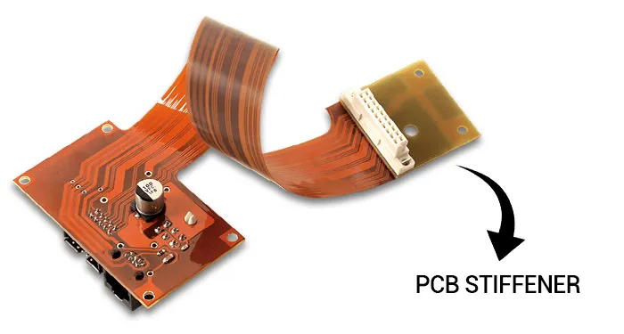
Flexible PCB stiffeners are reinforcing elements attached to specific areas of a flex circuit to provide mechanical support. They counteract the natural flexibility of base materials like polyimide, which can lead to warpage, trace cracking, or component detachment during handling, insertion, or operation. In high-reliability applications, stiffeners ensure stable platforms for soldering surface-mount devices and connectors. Without them, flex PCBs risk failure in automated assembly processes or under repeated flexing. Industry standards such as IPC-2223 outline requirements for their integration to maintain electrical performance and structural integrity. Ultimately, stiffeners balance flexibility with durability, making them essential for modern embedded systems.
Stiffeners matter because flex PCBs often interface with rigid components in hybrid assemblies. They prevent excessive deflection that could stress copper conductors or delaminate coverlayers. By distributing loads evenly, stiffeners reduce fatigue in bend zones adjacent to rigid sections. Engineers specify them based on cycle life requirements and environmental factors like vibration. Proper implementation aligns with qualification tests for mechanical reliability.
Flexible PCB Stiffener Materials
Selecting appropriate flexible PCB stiffener materials depends on the application's mechanical, thermal, and assembly needs. FR4, a glass-epoxy laminate, offers high rigidity and is the most common choice for supporting heavy connectors or dense component populations. It provides a flat, stable surface ideal for automated pick-and-place operations. Polyimide stiffeners, often in film form, deliver a balance of stiffness and flexibility, making them suitable for zero-insertion-force connectors where slight conformance is beneficial. Metal options like stainless steel or aluminum add formability and heat dissipation but increase weight and cost.
FR4 stiffeners excel in scenarios requiring maximum support due to their compressive strength. They bond well with thermal-set adhesives, ensuring long-term adhesion under thermal cycling. Polyimide maintains dimensional stability across wide temperature ranges, preventing mismatches with the flex base. Stainless steel suits formed bends or high-vibration environments, while aluminum aids in thermal management for power components. Engineers evaluate CTE compatibility to avoid stresses at interfaces.
Material choice influences overall PCB reliability. For instance, FR4 pairs effectively with epoxy adhesives for robust lamination. Polyimide films stack in layers for customizable thickness. Metals require precise etching or routing for alignment. Each type supports specific flexible PCB component support needs, from SMT pads to edge connectors.
Flexible PCB Stiffener Design Considerations
Effective flexible PCB stiffener design starts with defining the reinforcement zone's outline to fully encompass the supported area plus margins. The stiffener should extend beyond component footprints by at least 1 mm to distribute bending stresses. Overlap with the coverlay by about 0.75 mm relieves concentration at edges and acts as a strain relief. Thickness typically ranges from 0.1 mm to 1.5 mm, scaled to load requirements without adding unnecessary mass. Adhesive selection, whether pressure-sensitive or thermally cured, ensures void-free bonds compliant with lamination processes.
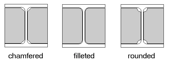
Flexible PCB designs incorporate fillets at corners to minimize stress risers during flexing. Registration features like fiducials aid precise alignment during attachment. For multilayer flex, stiffeners align with rigid sections in rigid-flex hybrids. IPC-2223 provides guidelines on material stack-ups and bend radii near stiffeners to prevent cracking. Simulation tools verify warpage under thermal loads.
Hybrid designs combine materials, such as FR4 with polyimide caps for tuned flexibility. Edge treatments prevent peeling during insertion. Thermal expansion alignment prevents delamination in reflow soldering.
Flexible PCB Stiffener Placement Strategies
Strategic flexible PCB stiffener placement targets high-stress zones like connector tails, IC mounting areas, and mounting holes. Place them directly beneath fine-pitch components to provide a rigid base that resists deflection during soldering or testing. In dynamic applications, position stiffeners adjacent to static bend lines to shield traces from fatigue. Avoid placing them in continuous flex paths, as this defeats the board's purpose. Multiple stiffeners on a single board require spaced placement to prevent thermal bridging issues.
For edge connectors, stiffeners reinforce the insertion tail, ensuring reliable mating cycles. Under ball-grid arrays or QFNs, they prevent substrate bounce during reflow. In wearables or automotive sensors, placement counters vibration-induced resonance. Factory processes favor symmetric placement for uniform lamination pressure.
Placement influences signal integrity by stabilizing ground planes. Overlaps ensure seamless transitions to flex regions. Testing validates placement through cyclic bending per IPC-6013.
Enhancing Flexible PCB Component Support
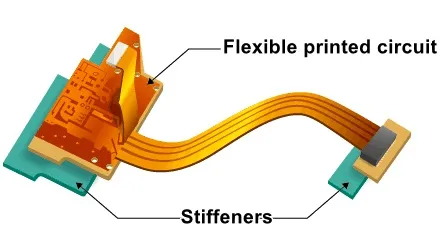
Flexible PCB component support relies on stiffeners to create rigid islands amid flexible tails. They prevent pad lifting or trace tears when components experience shear forces during operation. For SMT assemblies, stiffeners maintain coplanarity, improving solder paste release and joint formation. In through-hole scenarios, they align vias precisely for wave soldering. This support extends to shielding delicate passives from handling damage.
Stiffeners under BGAs distribute pressure evenly, reducing voiding risks. Connectors gain insertion force stability, preventing whisker formation in tin-plated tails. Vibration damping comes from material damping properties. Polyimide options flex slightly with the board, accommodating tolerances.
Component density drives stiffener sizing. Dense arrays need full-area coverage. Heat-generating parts benefit from metal stiffeners' conductivity.
Best Practices for Implementation
Adhere to best practices by specifying stiffeners in fabrication drawings with clear stack-up views and tolerances. Use thermally cured adhesives for high-reliability bonds, avoiding outgassing in vacuum environments. Validate designs through finite element analysis for stress distribution. Perform qualification via bend cycling and thermal shock tests aligned with IPC-6013. Collaborate with manufacturers early to optimize panelization for stiffener lamination.
Layer multiple thin stiffeners for fine thickness control. Etch registration holes for alignment. Monitor adhesive cure profiles to prevent voids. Post-attachment inspections check for delamination using ultrasonics.
Sustainability favors recyclable materials like FR4. Documentation includes material datasheets for traceability.
Conclusion
Flexible PCB stiffeners are vital for bridging flexibility and rigidity, ensuring reliable performance in demanding applications. By selecting optimal flexible PCB stiffener materials, refining designs, and strategic placement, engineers enhance flexible PCB component support and overall durability. Compliance with standards like IPC-2223 and IPC-6013 minimizes risks and streamlines manufacturing. Integrating these elements early in the design cycle yields robust assemblies with extended lifecycles. As flex technologies advance, stiffeners will continue supporting innovative, compact electronics.
FAQs
Q1: What are the most common flexible PCB stiffener materials?
A1: FR4 provides rigid support for connectors and components, while polyimide offers flexibility with stiffness for ZIF applications. Stainless steel and aluminum handle high vibration or thermal needs. Selection depends on CTE matching and assembly processes. These materials bond via adhesives, ensuring long-term reliability without compromising flex performance.
Q2: How does flexible PCB stiffener placement affect reliability?
A2: Placement under components and connectors prevents stress concentrations during bending or vibration. Extend beyond footprints by 1 mm and overlap coverlay for strain relief. Avoid flex zones to maintain dynamic capability. Proper positioning aligns with IPC-2223, reducing failures in cyclic environments.
Q3: What key factors influence flexible PCB stiffener design?
A3: Design considers thickness, overlap, and shape to distribute loads evenly. Fillets reduce stress risers, and registration aids alignment. Adhesive type ensures bond strength. Simulate for warpage, targeting component support needs. Standards guide stack-ups for rigid-flex transitions.
Q4: Why are stiffeners crucial for flexible PCB component support?
A4: They create stable platforms resisting deflection during soldering and operation. This prevents solder joint cracks and pad damage. Materials like FR4 enhance coplanarity for SMT. In vibration-prone uses, they dampen resonance. Result: higher assembly yields and field reliability.
References
IPC-2223 - Sectional Design Standard for Flexible/Rigid-Flex Printed Boards. IPC
IPC-6013 - Qualification and Performance Specification for Flexible Printed Boards. IPC


