Introduction
High-power LEDs have transformed lighting applications, offering energy efficiency and long lifespans, but their performance hinges on effective thermal management. Excessive heat generated by these LEDs can lead to reduced luminous output, accelerated degradation, and premature failure. Metal-backed PCBs, particularly aluminum PCB LED designs, address these challenges by providing superior heat dissipation pathways directly from the LED junction to the ambient environment.
In LED PCB thermal management, the choice of substrate material becomes critical for maintaining optimal operating temperatures. Engineers designing high power LED PCB systems must prioritize substrates that minimize thermal resistance while ensuring mechanical reliability. This deep dive explores how metal-backed PCB for LED lighting enhances performance through structured thermal pathways and factory-proven manufacturing techniques.
What Are Metal-Backed PCBs and Their Role in LED Applications
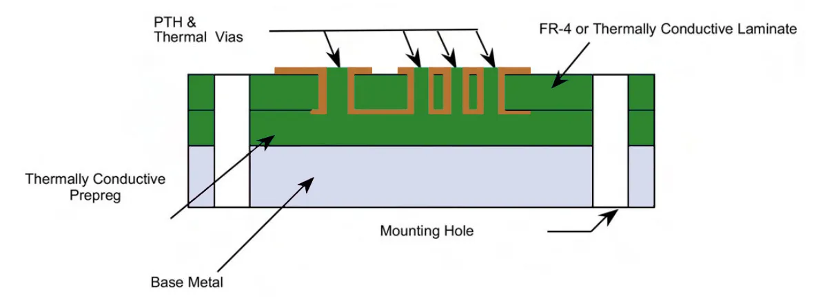
Metal-backed PCBs, often referred to as metal core printed circuit boards, consist of a thin copper circuit layer bonded to a thermally conductive dielectric, which sits atop a robust metal base, typically aluminum. This construction diverges from standard FR-4 boards by integrating a high-conductivity metal core that acts as a heat sink, ideal for LED heat dissipation PCB requirements. In high power LED PCB contexts, the aluminum base efficiently spreads heat laterally and vertically, preventing hotspots under LED chips. Factory production of these boards follows precise lamination processes to ensure strong interfacial bonds between layers, minimizing delamination risks during thermal cycling. For electric engineers, understanding this stackup is essential when specifying boards for demanding environments like street lighting or industrial fixtures.
The relevance of metal-backed PCB for LED lighting stems from the power densities in modern LED arrays, where wattages exceed those manageable by conventional substrates. Aluminum PCB LED configurations allow direct mounting of LEDs onto the board, leveraging the metal core for passive cooling without additional heatsinks in many cases. This integration simplifies assembly and reduces overall system costs while boosting reliability. Manufacturers emphasize controlled thermal expansion matching between the dielectric and metal base to avoid warpage, a common pitfall in high-heat applications.
The Critical Need for LED PCB Thermal Management
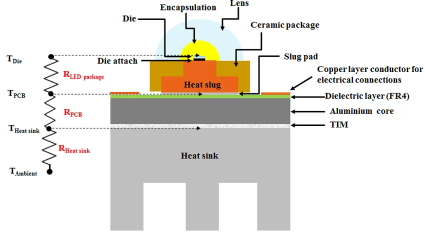
LED performance degrades rapidly when junction temperatures exceed safe thresholds, leading to color shifts, efficiency drops, and shortened operational life. Effective LED PCB thermal management ensures heat is conducted away from the semiconductor die, preserving photon output and electrical characteristics. High power LED PCB designs face amplified challenges due to concentrated heat fluxes from densely packed chips. Without proper dissipation, thermal runaway can occur, compromising the entire lighting module. Engineers must model heat flow from junction to board to ambient, accounting for convection, radiation, and conduction modes.
In industry practice, metal-backed substrates outperform FR-4 by orders of magnitude in thermal conductivity, enabling sustained high-lumen operation. For instance, aluminum cores facilitate direct heat spreading, reducing the need for complex via arrays or external cooling. This matters in applications where space constraints limit airflow, such as compact automotive headlights or display backlights. Factory-driven insights reveal that consistent thermal performance relies on uniform base thickness and surface finish to maximize contact with housings or fins.
Thermal Transfer Mechanisms in Metal-Backed PCBs
Heat from an LED chip primarily transfers via conduction through the die attach, copper pad, dielectric layer, and into the metal base. The dielectric's low thermal resistance is key, as it bridges the electrical insulation needs with efficient phonon transport to the aluminum. In aluminum PCB LED setups, lateral spreading within the base equalizes temperatures across larger areas, mitigating gradients that cause solder joint fatigue. Vertical conduction to chassis-mounted heatsinks further enhances dissipation in high power LED PCB systems. Engineers analyze these paths using finite element models, focusing on interface resistances that dominate overall thermal impedance.
Convection and radiation play secondary roles, but optimized aluminum board designs incorporate features like extended copper planes to boost emissivity. The metal base's high specific heat capacity buffers transient loads during dimming cycles or power surges. Compared to standard boards, metal-backed PCB for LED lighting reduces junction-to-case thermal resistance by channeling heat directly outward. Factory processes ensure dielectric thickness uniformity, as variations directly impact conductivity paths.
Standards like JEDEC JESD51-51 guide thermal characterization of LED packages, emphasizing metrics such as junction-to-board resistance that align with metal-backed PCB capabilities. This standard-aligned approach helps engineers validate designs against real-world operating conditions.
Design Best Practices for Optimal Heat Dissipation
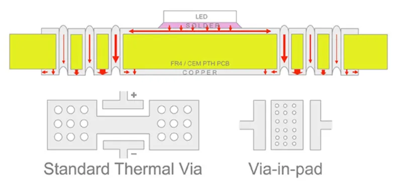
Position LEDs over the metal core regions, avoiding edges where spreading efficiency drops, to maximize LED heat dissipation PCB effectiveness. Incorporate thermal vias under die pads, filled with high-conductivity paste, to bridge copper and base layers without compromising electrical isolation. Wide copper pours and solid ground planes on the top side distribute heat evenly before it reaches the dielectric. For high power LED PCB arrays, segment the layout into thermal zones matched to airflow patterns in the fixture. Maintain dielectric thickness below 150 microns where possible, balancing voltage standoff with thermal performance.
Surface treatments like anodizing on the aluminum base improve emissivity for radiation cooling, while mechanical dimples enhance convective transfer. Simulate stackup interactions per IPC-2221 guidelines to predict warpage under thermal stress. Engineers should specify base thicknesses from 1.0 to 3.0 mm based on power density, ensuring compatibility with assembly processes.
Multi-layer designs route signals away from heat sources, using blind vias to preserve core integrity. Factory feedback stresses panel-level uniformity to avoid bow and twist during reflow.
Manufacturing Insights for Reliable Aluminum PCB LED Boards
Producing metal-backed PCB for LED lighting demands specialized lamination under high pressure and temperature to fuse the dielectric to aluminum without voids. Etching the copper layer requires controlled chemistry to prevent undercutting that could expose the core. Solder mask application must withstand thermal shock, often using high-Tg materials suited for LED reflow profiles. Drilling and plating vias demands precision to penetrate the dielectric cleanly without base damage. Post-fabrication, boards undergo thermal cycling tests to verify interfacial adhesion.
IPC-4101 specifications for base materials ensure consistency in metal-core laminates, covering thickness tolerances and peel strength critical for LED PCB thermal management. Manufacturers apply these to qualify lots, reducing field failures from delamination. Surface machining or chemical cleaning prepares the base for housing attachment, optimizing contact thermal resistance.
Common Challenges and Troubleshooting in Deployment
Warpage arises from CTE mismatches between copper, dielectric, and aluminum during high-temperature operation, leading to LED misalignment or joint cracks. Mitigate by selecting low-CTE dielectrics and symmetric stackups. Delamination at interfaces signals poor lamination or contamination, detectable via C-scan ultrasound in quality control. Excessive via thermal resistance indicates plating voids, addressable by electroplating over electroless seed layers. Hotspot persistence under LEDs points to dielectric hotspots, resolved by thinner films or higher filler content.
In high power LED PCB use, monitor board-level temperatures with IR thermography during prototype validation. Factory-driven adjustments, like optimized cure cycles, prevent these issues upstream.
Performance Advantages in Real-World LED Systems
Deploying aluminum PCB LED in street lighting sustains high flux over years by keeping junctions cool, extending maintenance intervals. Automotive applications benefit from vibration resistance alongside thermal prowess, enduring shock without performance loss. Industrial high-bay fixtures leverage large-area boards for uniform illumination without droop. Overall, these substrates enable brighter, more reliable systems by decoupling heat from electrical design constraints. Engineers gain flexibility in power scaling without proportional cooling complexity.
Conclusion
Metal-backed PCBs revolutionize LED performance by mastering thermal management, from conduction pathways to manufacturing precision. Aluminum PCB LED and similar designs deliver unmatched heat dissipation for high power applications, guided by standards like IPC-2221 and JEDEC JESD51-51. Electric engineers can boost efficiency and longevity by integrating these boards thoughtfully, focusing on layout, materials, and process controls. Prioritizing LED PCB thermal management ensures systems meet demanding reliability targets in diverse environments.
FAQs
Q1: What is a metal-backed PCB for LED lighting, and why choose it over FR-4?
A1: Metal-backed PCB for LED lighting features an aluminum core with a thermally conductive dielectric and copper traces, optimized for heat spreading. Unlike FR-4's low conductivity, it efficiently conducts heat from LED junctions, reducing temperatures and extending life. Factory production ensures CTE matching to prevent warpage, enabling higher power without added heatsinks and simplifying assemblies.
Q2: How does LED PCB thermal management improve with aluminum PCB LED?
A2: Aluminum PCB LED enhances thermal management through superior conduction via the metal base, minimizing thermal resistance from chip to ambient. Heat spreads laterally, avoiding hotspots that degrade efficiency. Engineers benefit from direct mounting and passive cooling, aligned with JEDEC thermal metrics, while manufacturing controls dielectric bonds for reliability under thermal cycling.
Q3: What design tips optimize high power LED PCB heat dissipation?
A3: Use thermal vias under pads, wide copper pours for spreading, and thin dielectrics per IPC-2221. Position LEDs centrally over the core and match base thickness to power load. Simulate temperature gradients to refine layouts, and verify via integrity and dielectric uniformity through factory specifications to sustain performance.
Q4: Why is LED heat dissipation PCB crucial for lifespan in high-power applications?
A4: Effective heat dissipation prevents junction overheating, which accelerates phosphor degradation and solder fatigue. Metal-backed boards channel heat efficiently, maintaining output over long service hours. Standards-guided characterization supports validation, avoiding excessive derating and maximizing reliability and ROI in demanding lighting systems.
References
IPC-4101 - Specification for Base Materials for Rigid and Metal-Core Printed Boards. IPC
IPC-2221B - Generic Standard on Printed Board Design. IPC
JEDEC JESD51-51 - Implementation of the Electrical Test Standard for LED Packages. JEDEC


