Introduction
Copper clad laminate (CCL) forms the foundation of every printed circuit board (PCB), serving as the insulating substrate that supports copper traces and components. Engineers selecting CCL must balance electrical performance, thermal reliability, and mechanical stability to meet application demands. This guide explores CCL types, key properties, and selection criteria tailored for electric engineers designing high-reliability boards. From standard FR-4 copper clad laminate to specialized high-frequency CCL, understanding these materials ensures optimal PCB performance. Factors like operating environment, signal speed, and manufacturing constraints guide the choice among diverse CCL types. By aligning material selection with project needs, engineers can avoid common pitfalls such as delamination or signal loss.
What Is Copper Clad Laminate (CCL)?
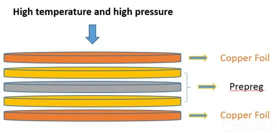
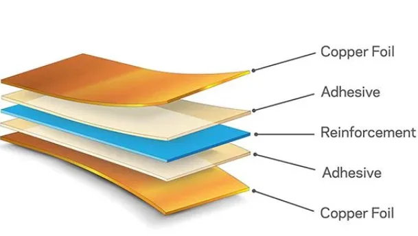
CCL consists of a thin sheet of copper foil bonded to one or both sides of a reinforced insulating substrate, typically a resin-impregnated fabric or paper. The substrate provides mechanical strength and electrical insulation, while the copper enables circuit patterning through etching. Common substrates include woven glass fabric with epoxy resin or cellulose paper cores, each influencing final board properties. Manufacturing involves stacking prepregs, which are partially cured resin sheets, under heat and pressure to form multilayer boards. CCL quality directly impacts PCB yield, as defects like voids or poor adhesion propagate through assembly. Engineers specify CCL thickness, copper weight, and surface finish based on trace width and current-carrying requirements.
Why Choosing the Right CCL Matters
Selecting inappropriate CCL leads to failures like warpage, caf (conductive anodic filamentation), or impedance mismatches in high-speed designs. For instance, low-Tg materials degrade under lead-free soldering temperatures, causing board delamination. In high-frequency applications, dielectric constant variations distort signal integrity, increasing bit error rates. Cost pressures tempt engineers toward basic CCL types, yet premium options yield long-term savings via higher reliability. Compliance with standards like IPC-4101 ensures consistent material performance across suppliers from CCL manufacturers. Proper selection aligns with application lifecycles, from consumer electronics to aerospace, where downtime costs escalate rapidly.
CCL Types: Overview and Comparisons
CCL types vary by reinforcement material, resin system, and performance class, categorized under IPC-4101 specifications. Grade N for FR-4 copper clad laminate uses E-glass fabric with brominated epoxy, offering balanced properties for most applications. CEM-1 copper clad laminate employs cellulose paper core with phenolic resin faces, suiting single-sided or double-sided low-cost boards. High-frequency CCL incorporates low-loss resins like PTFE or modified epoxies on ceramic-filled substrates for microwave circuits. Other variants include CEM-3 with glass-mat core for multilayer economic boards and polyimide-based for extreme temperatures. Engineers compare these based on Tg, CTE, and Df to match specific needs.
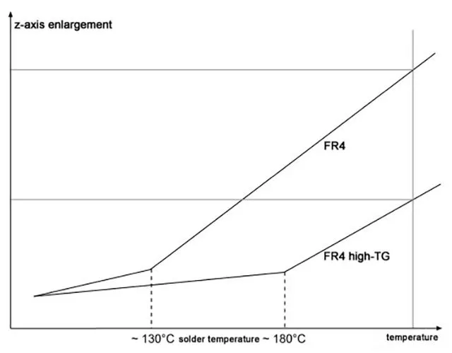
FR-4 copper clad laminate dominates due to its versatility, with standard grades exhibiting Tg around 130-140°C and CTE matched to copper for multilayer stability. It resists flammability per UL94 V-0 and handles soldering reliably. CEM-1 copper clad laminate, lighter and cheaper, suits punchable prototypes but shows higher moisture absorption, risking hydrolysis in humid environments. High-frequency CCL prioritizes low dielectric constant (Dk <3.5) and dissipation factor (Df <0.005) for minimal signal attenuation above 1 GHz. Polyimide CCL withstands 260°C continuous operation, ideal for downhole or automotive underhood use. Selection hinges on layering complexity and cost targets.
Key Properties of CCL to Evaluate
Glass transition temperature (Tg) marks the shift from glassy to rubbery state, critical for thermal cycling reliability. Materials with Tg above 170°C prevent resin softening during reflow, reducing Z-axis expansion mismatches. Coefficient of thermal expansion (CTE) alignment between CCL and copper foil minimizes stress in vias and pads, per IPC-TM-650 test methods. Dielectric properties, including Dk and Df, dictate signal propagation speed and loss in high-speed designs. Moisture absorption influences insulation resistance and caf resistance, with low values essential for class 3 assemblies. Copper foil parameters like roughness (Rz) affect skin effect losses and adhesion strength, measured via peel tests.
Thermal conductivity, though modest in standard epoxies (0.3-0.5 W/mK), improves in filled resins for power electronics. Dimensional stability resists warpage during lamination, assessed by bow and twist limits in IPC-6012. Halogen-free options reduce smoke in burning scenarios, aligning with environmental directives. Engineers use datasheets from CCL manufacturers to verify these against J-STD-001 requirements for soldering survivability. Peel strength exceeds 1.5 N/mm for robust plating adhesion. Flame retardancy, tracked via UL ratings, ensures safety in enclosed assemblies.
FR-4 Copper Clad Laminate: The Workhorse Material
FR-4 copper clad laminate excels in consumer, industrial, and telecom boards due to cost-effectiveness and process maturity. Standard FR-4 uses 2116 or 1080 glass styles for balanced drillability and resolution. High-Tg FR-4 variants suit thick copper multilayers, maintaining planarity post-lamination. Engineers specify FR-4 for its predictable etch factors and compatibility with sequential lamination. Drawbacks include moderate Df limiting GHz applications, prompting hybrids with high-frequency CCL cores. Factory insights reveal FR-4's dominance in 80% of volume production, per process yields.
CEM-1 Copper Clad Laminate: Cost-Effective Choice
CEM-1 copper clad laminate targets low-layer-count boards like power supplies or relays, leveraging paper core for machinability. Its phenolic resin provides punch-through ease, reducing tooling costs versus glass-epoxy. However, higher CTE in Z-axis demands careful via design to avert cracking. Suitable for wave soldering, it absorbs more moisture, necessitating bake-out per IPC-1601. Engineers favor CEM-1 for prototypes where density lags FR-4. Transition to CEM-3 extends usability to four-layer boards with improved rigidity.
High-Frequency CCL: Performance for RF and Microwave
High-frequency CCL employs hydrocarbons, PPE, or PTFE resins with quartz or ceramic fillers for Dk stability over frequency and temperature. Low Df preserves phase linearity in radar or 5G antennas. Hybrid stacks combine FR-4 outers with high-frequency CCL inners for cost control. Sequential build-up processes accommodate thin dielectrics down to 50μm. Engineers model insertion loss using Df curves from 100MHz to 40GHz. Thermal management challenges arise from lower Tg in some formulations, offset by metal cores.
Practical Selection Criteria for Engineers
Match CCL to electrical demands: low-Dk for high-speed, high-Tg for thermal stress. Compute layer stack CTE balance using supplier models to predict warpage under IPC-TM-650 2.4.4. Review copper weight (1oz standard, 2oz for power) against current density limits. Factor lead times from CCL manufacturers, as exotic types extend 12+ weeks. Prototype with small panels to validate drill smear and desmear efficacy. Simulate reliability via FEA for CTE mismatch in BGA packages.
Manufacturing and Quality Considerations
Lamination parameters like ramp rates influence void-free cores, per IPC-4101B. Plasma cleaning enhances adhesion on high-frequency CCL. Solder mask compatibility tests verify insulation post-reflow. Incoming inspection per IPC-TM-650 2.3.25 checks resin content uniformity. Electrical tests confirm dielectric breakdown above 30kV/mm. Traceability from CCL manufacturers ensures batch consistency.
Troubleshooting Common CCL Issues
Warpage exceeds 0.75% in mismatched CTE stacks; remedy via symmetric builds. Caf initiates from drill smear residue, mitigated by permanganate desmear. Delamination traces to moisture entrapment; enforce MSL1 storage. Signal skew in high-frequency CCL arises from unequal line lengths; equalize via length-tuning. Peel failures signal weak foil bond; audit surface treatment.
Conclusion
Choosing the right CCL hinges on aligning CCL types like FR-4 copper clad laminate, CEM-1 copper clad laminate, and high-frequency CCL with application specifics. Key properties such as Tg, CTE, and dielectric constants drive reliability and performance. Standards like IPC-4101 guide specifications, while factory practices ensure manufacturability. Engineers benefit from systematic evaluation, balancing cost and capability. This approach yields robust PCBs across industries. Future trends favor low-loss, lead-free materials for denser, faster designs.
FAQs
Q1: What are the main CCL types for PCB engineers?
A1: CCL types include FR-4 copper clad laminate for general use, CEM-1 copper clad laminate for cost-sensitive singles, and high-frequency CCL for RF signals. FR-4 offers Tg stability, CEM-1 aids machinability, and high-frequency variants minimize losses. Select per IPC-4101 grades matching Dk and thermal needs. Factory validation confirms drill and plate compatibility.
Q2: How does FR-4 copper clad laminate compare to CEM-1?
A2: FR-4 copper clad laminate uses glass-epoxy for multilayers with low CTE, while CEM-1 employs paper-phenolic for economical doubles. FR-4 resists caf better, suiting high-density; CEM-1 punches easily but absorbs moisture. Both meet UL94 V-0, but FR-4 handles reflow superiorly. Engineers choose based on layer count and environment.
Q3: When should I use high-frequency CCL?
A3: Opt for high-frequency CCL in designs exceeding 1GHz, like 5G or radar, needing low Df and stable Dk. It outperforms FR-4 in insertion loss but costs more. Hybrid stacks optimize economics. Verify via TDR for impedance control. CCL manufacturers supply tuned formulations.
Q4: What standards govern CCL selection from manufacturers?
A4: IPC-4101 specifies CCL types and properties, ensuring uniformity from CCL manufacturers. IPC-TM-650 outlines tests for Tg and peel. J-STD-020 classifies MSL handling. Compliance aids qualification.
References
IPC-4101E — Specification for Base Materials for Rigid and Multilayer Printed Boards. IPC, 2017
IPC-TM-650 — Test Methods Manual. IPC, 2020
IPC-6012E — Qualification and Performance Specification for Rigid Printed Boards. IPC, 2018


