Introduction
Flexible printed circuit boards, or flex PCBs, enable compact designs in applications ranging from consumer electronics to medical devices. Engineers must differentiate between dynamic and static bending to ensure long-term reliability. Dynamic flexible PCBs endure repeated flexing cycles, while static flexible PCBs experience bending primarily during installation. Understanding flexible PCB bending stress and fatigue becomes critical for longevity, as improper design leads to failures like trace cracks or delamination. This article explores the distinctions, mechanisms, and best practices aligned with industry standards. By applying structured engineering principles, designers can optimize flex PCBs for demanding environments.
Defining Dynamic and Static Bending in Flexible PCBs
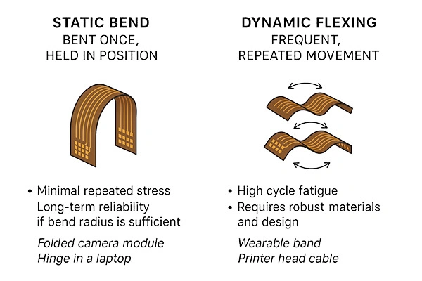
Static bending occurs when a flex PCB assumes a fixed curved shape after a single or limited number of bends, typically fewer than 100 cycles over its lifetime. In contrast, dynamic bending involves continuous or high-cycle flexing, often thousands to millions of cycles in operational use. The IPC-2223 standard classifies these as static flex type A for installation bends and dynamic flex type B for repeated motion. This distinction matters because static applications tolerate tighter radii, while dynamic ones demand greater durability to resist fatigue. Engineers select materials and layouts accordingly to manage flexible PCB bending stress. Ignoring these differences risks premature failure in products like wearables or robotic joints.
Static flexible PCBs appear in hinged displays or cable replacements where the bend remains constant post-assembly. Dynamic flexible PCBs power moving parts, such as printer heads or foldable screens, subjecting copper traces to ongoing strain. Flexible PCB fatigue manifests differently: static cases involve creep under sustained load, whereas dynamic scenarios accelerate crack propagation. Relevance grows with miniaturization trends, as thinner substrates amplify stress concentrations. Design choices early in the process prevent costly iterations. Procurement teams benefit from specifying bend types upfront to align manufacturing capabilities.
Engineering Mechanisms of Bending Stress and Fatigue
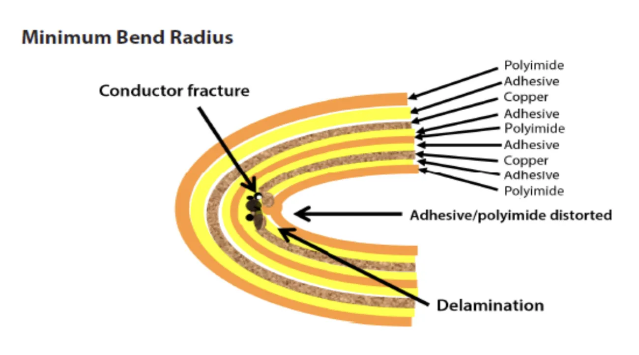
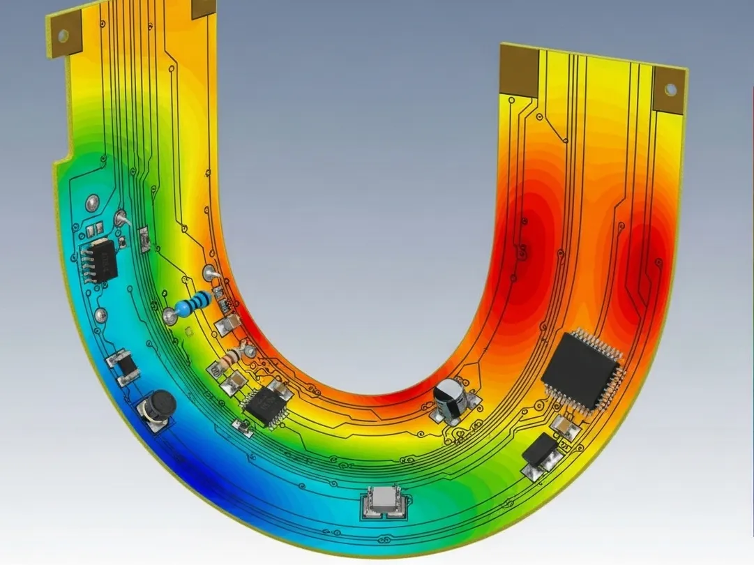
Flexible PCB bending stress arises from the strain gradient across the substrate thickness during curvature. The outer layers experience tensile stress, while inner layers endure compression, with the neutral axis ideally positioned to minimize conductor deformation. In static bending, sustained stress leads to viscoelastic creep in adhesives and dielectrics, potentially causing coverlay lift-off over time. Copper ductility plays a key role; electrodeposited copper suits static use due to its grain structure, but rolled annealed copper resists dynamic strain better. Engineers model stress using beam theory, where maximum strain equals thickness divided by twice the bend radius. Adhering to guidelines prevents exceeding material yield points.
Flexible PCB fatigue in dynamic applications follows cyclic loading principles akin to metal fatigue in mechanics. Each flex cycle introduces microcracks at trace edges or vias, propagating under repeated tension-compression. Factors like bend radius, cycle frequency, and temperature amplify damage accumulation via low-cycle or high-cycle fatigue regimes. Polyimide substrates offer high flexibility, yet adhesive interfaces degrade under shear. IPC-6013 qualification tests verify endurance through standardized bend cycles. Understanding these mechanisms allows predictive modeling for longevity estimates.
Stress risers, such as sharp bends or angular trace routings, concentrate flexible PCB bending stress, accelerating fatigue initiation. Traces perpendicular to the bend axis suffer highest strain, while parallel orientations distribute load evenly. Environmental factors like humidity exacerbate fatigue by softening adhesives, leading to interlayer slippage. Thermal expansion mismatches between copper and substrate induce additional cyclic stresses during operation. Mitigation starts with finite element analysis to simulate strain fields. Consistent application of these principles ensures robust designs.
Best Practices for Designing Long-Lasting Flex PCBs
Select substrate and copper types based on application: adhesiveless laminates with rolled annealed copper for dynamic flexible PCBs to enhance fatigue resistance. Maintain minimum bend radii per IPC-2223 tables, scaling with layer count; static bends allow tighter curves than dynamic ones requiring 20 times substrate thickness or more in severe cases. Route traces parallel to the bend line, using sinusoidal or curved patterns to equalize strain and avoid sharp corners. Position coverlay to protect conductors without creating stress points at edges. Incorporate annular rings around vias outside bend zones to prevent cracking.
Layer stackup optimization reduces overall thickness, easing flexible PCB bending stress. Single or double-sided constructions suffice for most dynamic uses, while multilayers demand careful adhesive control. Add stiffeners or frames at rigid-flex transitions to localize flexing and shield solder joints. Simulate dynamic cycles using accelerated testing protocols to validate designs pre-production. Control copper weight to 1 oz per square foot maximum in flex regions for strain relief. These practices extend service life significantly.
For assembly, support flex sections during soldering to avoid unintended bends, and use low-stress adhesives for reinforcements. In dynamic flexible PCB designs, segment long traces into shorter segments with jogs perpendicular to flex lines for redundancy. Monitor plating uniformity to ensure consistent ductility across conductors. Post-fabrication, perform bend endurance tests to confirm compliance. Documentation of bend specifications aids quality control. Engineers achieve longevity through iterative refinement grounded in mechanical reliability.
Troubleshooting Common Failures in Flex PCB Bending
Delamination often signals excessive static bending stress, traced to inadequate coverlay adhesion or humidity exposure. Inspect for voids via cross-sectioning and adjust cure cycles accordingly. In dynamic flexible PCB fatigue, trace fractures appear after simulated cycles; countermeasures include finer linewidths or redundant paths. Vias cracking at bend edges indicate poor placement; relocate to straight sections. Warpage from mismatched CTEs requires balanced stackups. Systematic failure analysis, combining microscopy and electrical testing, pinpoints root causes for redesign.
Conclusion
Distinguishing dynamic from static bending guides flexible PCB design toward superior longevity. Static flexible PCBs prioritize installation ease with moderate radii, while dynamic ones demand fatigue-resistant features like optimized copper and routing. Managing flexible PCB bending stress through standards like IPC-2223 and IPC-6013 ensures reliability. Practical steps, from material selection to simulation, yield durable solutions. Engineers applying these principles reduce field failures and enhance product performance. Future innovations will further refine flex capabilities for emerging applications.
FAQs
Q1: What differentiates a dynamic flexible PCB from a static flexible PCB?
A1: Dynamic flexible PCBs handle repeated bending cycles in operation, such as in moving mechanisms, requiring rolled annealed copper and larger bend radii for fatigue resistance. Static flexible PCBs bend once during assembly and hold position, allowing tighter radii and electrodeposited copper. IPC-2223 guidelines specify design classes A for static and B for dynamic. Proper classification prevents overdesign costs or early failures.
Q2: How does flexible PCB bending stress lead to fatigue failure?
A2: Flexible PCB bending stress creates strain gradients, with cyclic dynamic flexing propagating microcracks in copper traces and adhesives. Fatigue life depends on radius, cycle count, and material ductility. Static stress induces creep rather than rapid cracking. Testing per IPC-6013 verifies endurance. Designs with curved traces and adhesiveless builds extend cycles significantly.
Q3: What are key design rules for minimizing flexible PCB fatigue?
A3: Route traces parallel to bends with curved profiles to distribute strain evenly. Use minimum bend radii scaled to thickness, larger for dynamic applications. Avoid vias and heavy copper in flex zones. Reinforce with stiffeners at transitions. These practices, aligned with IPC standards, boost reliability in high-cycle uses.
Q4: When should engineers specify dynamic versus static flex in PCB designs?
A4: Specify dynamic for applications exceeding 100 bends, like wearables or hinges in motion. Static suits fixed curves post-install, such as cable harnesses. Evaluate lifecycle requirements early to select materials and radii. Mis-specification accelerates flexible PCB fatigue. Consult IPC-2223 for precise classifications.
References
IPC-2223D — Sectional Design Standard for Flexible/Rigid-Flexible Printed Boards. IPC, 2023
IPC-6013E — Qualification and Performance Specification for Flexible and Rigid-Flexible Printed Boards. IPC, 2024
IPC/TM-650 2.4.3 — Flexural Fatigue, Flexible Printed Wiring. IPC, 2018


