Introduction
The Game Gear PCB represents a compact engineering feat from early handheld gaming hardware, integrating logic, audio, and power functions into a portable form factor. Electronic hobbyists often encounter these boards when restoring vintage units, where technical details determine successful repairs. This technical guide explores the Game Gear PCB, with focus on audio PCBs, power PCB, and capacitor roles, providing practical insights for troubleshooting and maintenance. Understanding these elements helps hobbyists address common failures like distorted sound or power instability. By examining circuit principles and best practices, you can revive these boards effectively. Key sections include board overviews, operational mechanisms, and hands-on solutions tailored for home workshops.
What Is the Game Gear PCB and Why It Matters
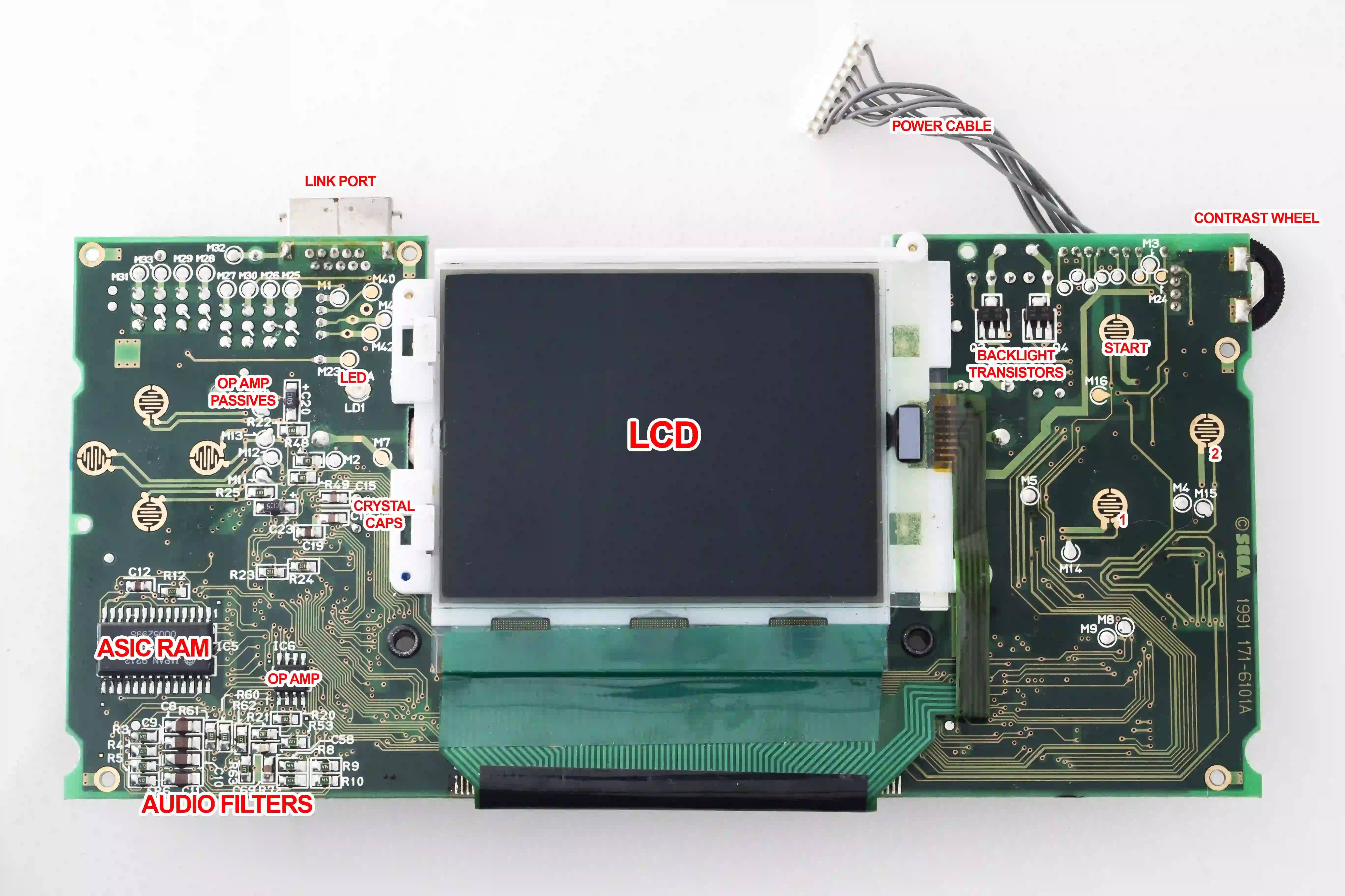
The Game Gear PCB consists of three primary boards: the main logic board, audio PCB, and power PCB, interconnected via ribbon cables and edge connectors. The main board handles processing, video generation, and memory, featuring custom ASICs and SRAM chips that vary by revision such as early twin-ASIC or later single-ASIC designs. Audio PCBs dedicate space to amplification circuits, while power PCBs convert battery voltage to stable rails for the system. These separations allow modular repairs but introduce failure points over time. For electronic hobbyists, mastering these boards matters because aging components lead to widespread issues in retro hardware collections. Proper knowledge ensures reliable performance and extends device lifespan without complex tools.
Capacitors play a pivotal role across all boards, acting as filters, couplers, and energy reservoirs in compact layouts. Failures here manifest as no power, faint audio, or dim visuals, making them a primary concern in this technical guide. Hobbyists value these insights for cost-effective fixes over full replacements. Board revisions influence capacitor placement and count, requiring version identification first. This modular design reflects engineering trade-offs for portability versus serviceability.
Technical Principles of Game Gear PCB Sections
The main PCB integrates core processing with video and system RAM, where electrolytic capacitors support voltage stability near memory and logic ICs. These components smooth supply ripples from the power board, preventing glitches in graphics or resets during gameplay. Surface-mount designs pack densely, optimizing space but challenging rework. Capacitors here often couple signals or filter noise in video circuits, maintaining signal integrity under battery fluctuations. Revisions like single-ASIC versions consolidate functions, reducing capacitor needs but concentrating stress points.
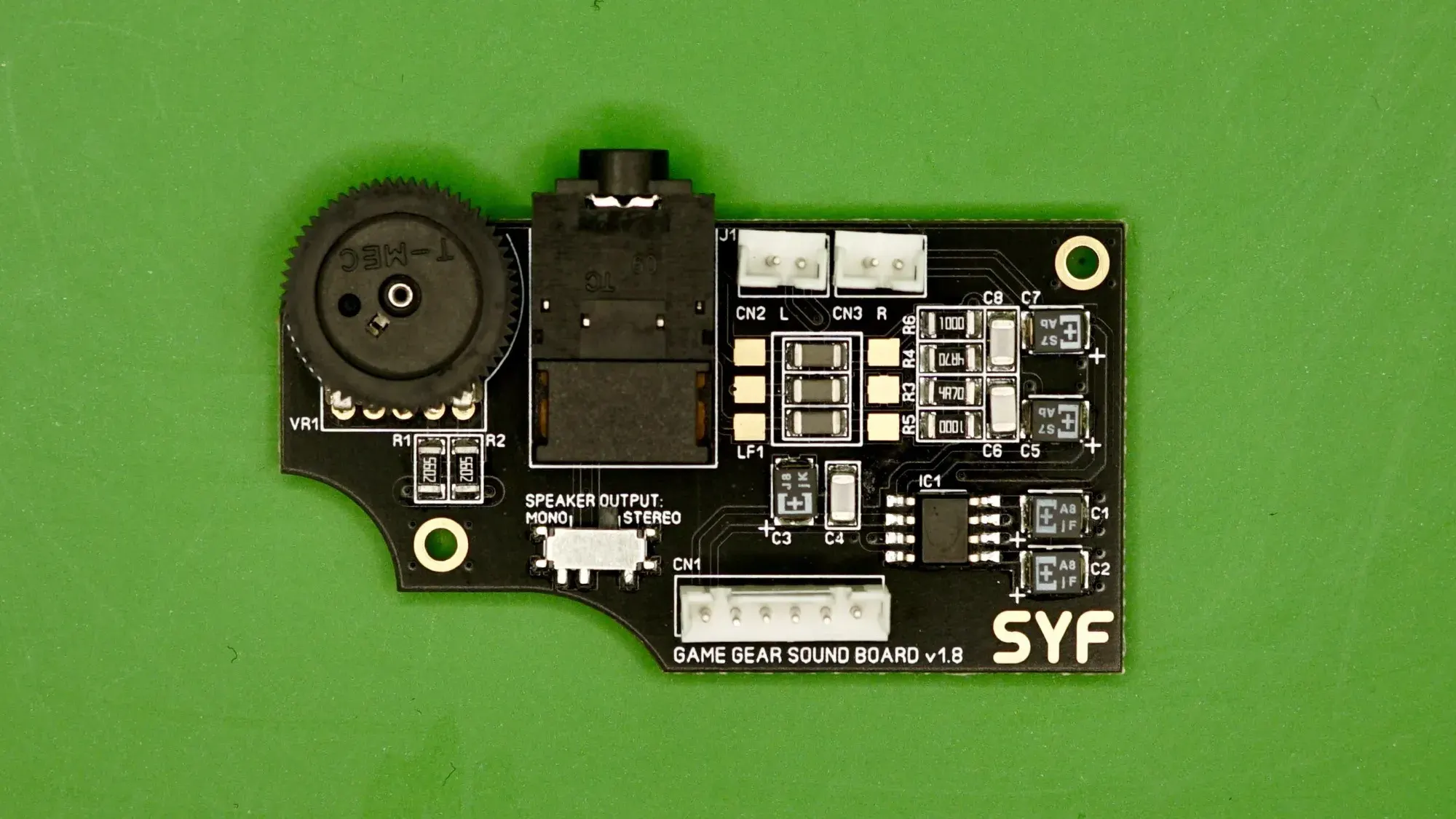
Audio PCBs focus on signal amplification, typically using a dedicated IC for stereo output with multiple electrolytic capacitors for DC blocking and ripple filtering. Input signals from the main board pass through coupling capacitors to prevent DC offset at the amplifier inputs, while output capacitors stabilize speaker drive. Bypass capacitors shunt high-frequency noise, ensuring clean sound reproduction. Low-voltage ratings suit the 5V rails, but electrolyte degradation alters capacitance over decades. This section demands precise orientation during replacement to avoid shorts.
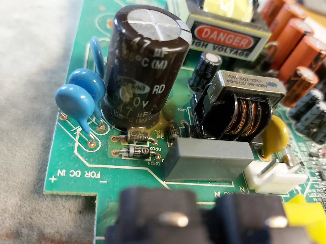
Power PCBs employ a DC-DC converter topology, generating multiple voltages from 6V batteries using switching regulators and inductors. Capacitors serve critical roles: input filters reduce battery noise, output bulk capacitors store charge for transient loads, and ceramic types handle high frequencies. A large reservoir capacitor smooths the 5V main rail, while smaller ones support auxiliary lines like 1.28V for logic. Inductor-capacitor pairs form LC filters post-switching to minimize ripple. Failures here cascade to the entire system, underscoring capacitor reliability in power delivery.
Following IPC-6012E qualification for rigid printed boards ensures these multilayer designs withstand thermal and mechanical stresses in handheld use. Electrolytic capacitors degrade via electrolyte evaporation or leakage, corroding pads and altering ESR, which spikes ripple voltages. In audio paths, increased ESR distorts waveforms; in power, it causes voltage droops under load. Surface-mount types accelerate failure due to thin legs and heat exposure during assembly.
Role of Capacitors in Game Gear PCBs
Capacitors dominate Game Gear PCB issues, with electrolytics prone to leakage after prolonged storage. On audio PCBs, clusters of similar values handle coupling and filtering, where failure mutes channels or introduces hum. Power PCBs feature larger axial types for bulk storage, absorbing battery dips during high-draw moments like screen refresh. Main boards use them sparingly for local decoupling, tying VDD to ground near IC pins. Polarity marks guide installation, as reversal leads to venting or explosion.
Leakage residue attacks copper traces, lifting pads and requiring jumper wires in repairs. Ceramic alternatives offer longevity but demand value matching to avoid circuit shifts. ESR rise degrades filtering, turning clean DC into noisy supplies that affect audio clarity or video contrast. Hobbyists test with multimeters for shorts or capacitance meters for degradation. IPC-A-600K acceptability criteria flag corrosion or delamination as rejects, guiding visual inspections.
Thermal cycling from battery heat accelerates electrolyte dry-out, common in stacked battery compartments. Vibration loosens joints, compounding issues. Modern replacements use low-ESR types for improved performance, though original tolerances suffice for stock operation.
Practical Solutions and Best Practices
Start repairs by disassembling to access boards, noting connector orientations. Inspect for bulging tops, crusty residue, or discolored pads signaling capacitor failure. Clean with isopropyl alcohol and flux remover before desoldering. Use hot air or iron with wick for SMD removal, adding fresh solder to pads first. Replace all electrolytics preemptively, matching footprint and voltage ratings at minimum.
Soldering follows J-STD-020E handling for moisture-sensitive devices: bake if needed, then reflow gently. For power PCBs, verify output voltages post-repair: stable 5V primary, with auxiliaries per schematic expectations. Audio boards benefit from symmetry in capacitor placement for balanced channels. Test under load with dummy batteries or resistors simulating draw.
Multimeter continuity checks inductors and IC pins on power boards prevent overlooking non-cap faults. Flux aids clean joints, minimizing cold solders. Reassembly includes insulating tape on power sections to avert shorts. These steps align with factory-driven quality control for sustained operation.
Troubleshooting Common Game Gear PCB Issues
No power often traces to power PCB: check battery contacts, then capacitors for shorts bridging pins. Dim screen or washed graphics point to main board filters failing, starving video ICs. Distorted or absent audio implicates audio PCB coupling caps, confirmed by scope ripple or substitution. Intermittent issues suggest loose connectors or cracked traces from cap leakage.
Systematic voltage rail probing isolates sections: 5V absent means power regulator fault; present but noisy indicates filter loss. Visual pad damage demands repair before powering. Overheating post-repair signals polarity errors or value mismatches.
Conclusion
The Game Gear PCB exemplifies compact electronics where audio PCBs, power PCB, and capacitors interplay for reliable performance. Grasping technical principles like filtering and coupling equips hobbyists for effective restores. Practical recapping resolves most faults, guided by visual standards and soldering care. These insights form a solid technical guide, empowering hands-on fixes. Regular maintenance preserves retro hardware joy for generations.
FAQs
Q1: Why do capacitors fail on Game Gear PCBs?
A1: Electrolytic capacitors in Game Gear PCBs degrade over time due to electrolyte evaporation, leakage, or thermal stress, common in audio PCBs and power PCB. This raises ESR, causing ripple in power rails or signal distortion in audio paths. Visual signs include bulging or residue. Replacing them restores function per IPC rework guidelines. Proactive swaps prevent corrosion spread.
Q2: How do I identify the version of my Game Gear PCB for repairs?
A2: Check ASIC markings on the main board: twin chips indicate VA0, single for VA1 or later. Audio and power PCBs have numbered revisions like 837-7998. Capacitor layouts vary slightly. Schematics aid confirmation. This ensures correct replacement parts for audio PCBs and power PCB.
Q3: What role do capacitors play in Game Gear audio PCBs?
A3: Capacitors on audio PCBs block DC, filter noise, and couple signals to the amplifier IC. Failures mute sound or add hum by passing offsets. Multiple low-voltage units per channel demand uniform replacement. Testing involves audio probes post-swap.
Q4: Can I use ceramic capacitors instead of electrolytic on power PCB?
A4: Ceramic types suit decoupling on power PCB but match bulk electrolytics with multiples in parallel for storage. They resist aging better, lowering ESR for cleaner rails. Verify circuit tolerance via substitution tests. Follow J-STD-001 soldering for reliability.
References
IPC-6012E — Qualification and Performance Specification for Rigid Printed Boards. IPC, 2017
IPC-A-600K — Acceptability of Printed Boards. IPC, 2020
J-STD-020E — Moisture/Reflow Sensitivity Classification. JEDEC, 2014
IPC-7711/7721 — Rework, Modification and Repair of Electronic Assemblies. IPC, 2020


