Introduction
Marine navigation electronics power critical systems like radar, GPS receivers, and autopilot controls, where failure can lead to catastrophic consequences. These devices operate in relentless conditions of high humidity, saltwater exposure, temperature fluctuations, and mechanical vibrations. PCB material selection emerges as a foundational factor in ensuring long-term reliability, as the substrate directly influences resistance to corrosion, thermal stress, and electrical degradation. Poor choices can accelerate delamination, conductive anodic filamentation, or insulation breakdown, compromising signal integrity and safety. Engineers must prioritize materials that balance performance, cost, and manufacturability while addressing marine-specific challenges. This article explores how marine PCB material selection impacts overall system dependability, drawing on key properties and comparisons to guide informed decisions.
The Harsh Realities of Marine Environments for Electronics
Marine settings expose PCBs to saltwater spray, which promotes ionic contamination and corrosion on exposed copper traces. High humidity levels often exceed 95%, fostering moisture ingress that lowers insulation resistance and triggers electromigration. Temperature swings from -40°C in polar routes to over 70°C in engine compartments induce thermal expansion mismatches, leading to cracks or warpage. Vibrations from waves and engines add fatigue stress, while pressure variations in submerged units demand robust mechanical integrity. These factors amplify the need for materials with low moisture absorption, high chemical resistance, and matched coefficients of thermal expansion. Without proper marine PCB material selection, even robust designs fail prematurely, underscoring the link between substrate choice and mission-critical reliability.
Key Material Properties Influencing PCB Reliability
Core properties like glass transition temperature (Tg), coefficient of thermal expansion (CTE), and moisture absorption dictate PCB performance in marine applications. High Tg materials resist softening during thermal cycling, preventing via barrel cracking. Low CTE minimizes stress at copper-plated through-hole interfaces, crucial under vibration. Dielectric strength and comparative tracking index (CTI) ensure insulation holds against voltage creepage in contaminated environments. Chemical resistance guards against saltwater-induced hydrolysis, while flexural strength counters mechanical shocks. Thermal conductivity aids heat dissipation from power components, avoiding hotspots that degrade solder joints. Engineers evaluate these via standardized tests to predict field behavior.
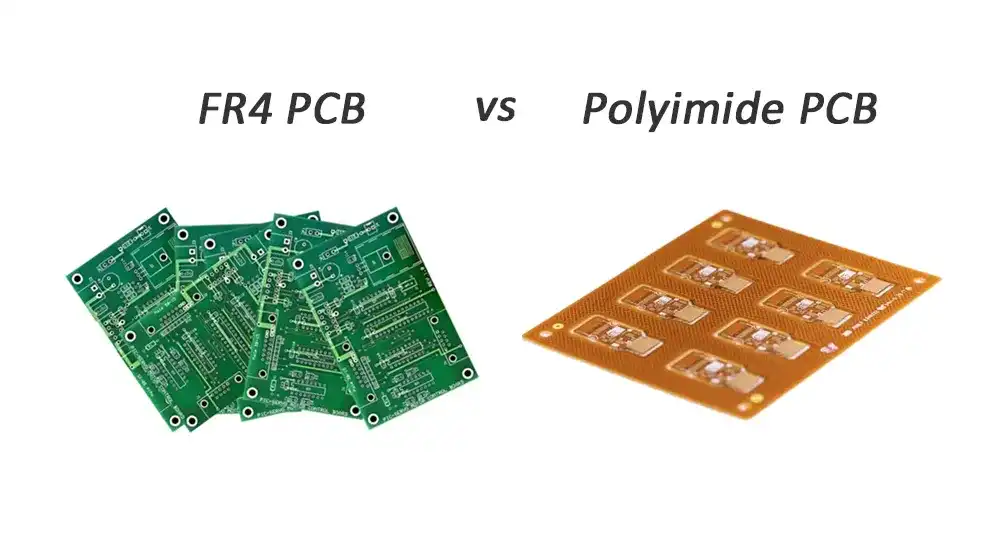
FR4 vs Polyimide: A Critical Comparison for Marine PCBs
FR4, a glass-reinforced epoxy laminate, serves as the baseline for cost-sensitive marine applications due to its mechanical rigidity and process compatibility. It offers adequate Tg around 130-180°C and low cost, but its higher moisture absorption risks swelling and delamination in humid conditions. Polyimide substrates excel with Tg exceeding 250°C, superior chemical stability, and lower outgassing, making them ideal for flexible or rigid-flex designs in extreme heat. In FR4 vs polyimide marine PCB scenarios, polyimide demonstrates better resistance to saltwater corrosion and thermal shock, though at higher expense. FR4 suits less demanding chartplotters, while polyimide fits high-reliability sonars. Selection hinges on lifecycle cost analysis, weighing upfront premiums against reduced failure rates.
High CTI PCB Materials: Combating Tracking in Humid Conditions
High CTI PCB material prevents surface tracking, where moisture and contaminants form conductive paths across insulators. CTI values above 600V enable closer trace spacing in compact navigation units, vital for high-density designs. Standard FR4 typically achieves CTI 175-250V, insufficient for saltwater-laden air, whereas specialized high-CTI variants exceed 600V through optimized resin formulations. In marine settings, salt deposits lower effective CTI, risking arcing during voltage surges from lightning or motors. Selecting high CTI materials aligns with reliability goals by enhancing creepage margins without enlarging footprints. Testing per industry protocols verifies performance under simulated contamination.
Thermal Management PCB Materials for High-Power Marine Systems
Power-hungry marine electronics like VHF radios generate significant heat, necessitating thermal management PCB material with enhanced conductivity. Standard laminates conduct poorly, relying on copper planes and vias for spreading, but metal-backed substrates like insulated metal base (IMB) offer direct aluminum or copper cores for superior dissipation. These reduce junction temperatures, extending component life amid poor convection in sealed enclosures. CTE matching prevents solder fatigue during engine bay exposures. Engineers integrate thermal vias arrays and thicker copper to augment base material efficacy. Proper selection averts thermal runaway, preserving signal accuracy in radar processing.
Achieving Saltwater Resistance with Specialized Laminates
Saltwater resistant PCB laminate prioritizes low water absorption and hydrolysis stability to block chloride ion penetration. Epoxy-based FR4 variants with hydrophobic additives limit ingress, but polyimide or phenolic resins provide inherent resistance via stable polymer chains. Conformal coatings amplify laminate protection, yet base material flaws undermine them over time. Delamination from osmotic swelling compromises multilayer integrity, inviting shorts. High-purity glass reinforcement and controlled resin cure enhance barrier properties. In prolonged exposure, these laminates maintain dielectric integrity, supporting uninterrupted operation.
Standards and Testing Protocols for Marine PCBs
IPC-6012 establishes qualification criteria for rigid PCBs, mandating thermal cycle and humidity bias tests relevant to marine stresses. IPC-TM-650 outlines methods for CTI, moisture absorption, and warpage evaluation, ensuring material consistency. These protocols simulate field conditions, like 85% RH at 85°C, to predict long-term degradation. Adherence to IPC Class 3 provisions guarantees high-reliability features, such as refined plating and minimal voids. IEC standards complement for environmental robustness, guiding conformal coating verification. Compliance verifies that marine PCB material selection withstands operational rigors.
Best Practices in Marine PCB Material Selection
Begin with environmental profiling to quantify exposure levels, then match materials via datasheets against Tg, CTI, and absorption specs. Prototype with accelerated life testing to validate FR4 vs polyimide marine PCB trade-offs. Incorporate design margins like wider clearances for lower CTI bases. Collaborate with fabricators on IPC-compliant processes to avoid contamination. Layer thermal management PCB material strategically under hotspots. Document rationale per risk assessments, facilitating audits and iterations.
Common Failure Modes and Troubleshooting
Saltwater corrosion manifests as dendritic growth, troubleshootable by switching to high-CTI, low-absorption laminates and ENIG finishes. Thermal mismatch causes via cracks; mitigate with low-CTE polyimide and simulation tools. Moisture-induced CAF demands bake-out pre-assembly and hermetic sealing. Vibration fatigue responds to flexible substrates or damping layers. Post-failure analysis via cross-sectioning reveals root causes, informing redesigns. Proactive material upgrades avert recurrences.
Conclusion
PCB materials profoundly shape the reliability of marine navigation electronics by countering corrosion, heat, and stress. Strategic marine PCB material selection, pitting FR4 against polyimide where apt, alongside high CTI and thermal management PCB material, fortifies designs. Saltwater resistant PCB laminate choices, validated against standards, ensure endurance. Engineers armed with these insights optimize for longevity, minimizing downtime in unforgiving seas.
FAQs
Q1: What factors drive marine PCB material selection for navigation systems?
A1: Marine PCB material selection hinges on resistance to saltwater, humidity over 95%, temperature extremes, and vibration. Prioritize low moisture absorption below 0.5%, high Tg over 170°C, and CTI exceeding 400V. Polyimide outperforms FR4 in chemical stability, while high-CTI variants prevent tracking. Testing per IPC protocols confirms suitability, balancing cost with field-proven durability.
Q2: How does FR4 vs polyimide marine PCB impact reliability?
A2: FR4 vs polyimide marine PCB comparison reveals polyimide's edge in Tg (250°C+ vs 130-180°C) and corrosion resistance, ideal for flex applications. FR4 suffices for rigid, moderate-stress boards but risks delamination in humidity. Polyimide's premium cost yields longer life in sonars or radars. Select based on flexibility needs and thermal cycling demands for optimal reliability.
Q3: Why choose high CTI PCB material in salty environments?
A3: High CTI PCB material resists tracking from saltwater contaminants, maintaining insulation at voltages over 600V. Standard materials fail under ionic films, causing shorts. It enables dense layouts without creepage hikes, crucial for compact nav gear. Pair with coatings for synergy, verified via contamination tests.
Q4: What thermal management PCB material suits marine power electronics?
A4: Thermal management PCB material like metal-core laminates excels in dissipating heat from amplifiers in enclosed spaces. They lower deltas T via high conductivity, preventing solder creep. Integrate with vias for uniform spread, essential amid poor airflow. Avoid standard FR4 for >50W dissipation to sustain performance.
References
IPC-6012E — Qualification and Performance Specification for Rigid Printed Boards. IPC, 2018
IPC-TM-650 — Test Methods Manual. IPC, 2023
IPC-4101E — Specification for Base Materials for Rigid and Multilayer Printed Boards. IPC, 2017


