Introduction
Thermal performance is a critical factor in the design and operation of printed circuit boards (PCBs). Excessive heat can degrade components, reduce reliability, and lead to system failures. For electrical engineers, understanding how to measure and manage PCB thermal performance is essential to ensure functionality and longevity. This article explores various methods to assess thermal behavior, including the use of thermocouples, infrared imaging, thermal cameras, temperature sensors, and simulation tools. By applying these techniques, engineers can identify hot spots, validate designs, and optimize cooling solutions. The focus will be on practical approaches and industry-standard practices to provide actionable insights for professionals in the field.
Why PCB Thermal Performance Matters
PCBs are the backbone of electronic systems, hosting components that generate heat during operation. If this heat is not dissipated effectively, it can cause thermal stress, component failure, or reduced performance. Measuring thermal performance helps engineers ensure that a PCB operates within safe temperature limits, as defined by standards such as IPC-6012E. Poor thermal management may lead to issues like solder joint cracking, material degradation, or circuit malfunctions. By accurately assessing heat distribution, engineers can make informed decisions about layout design, material selection, and cooling mechanisms, ultimately enhancing product reliability and safety.
Technical Principles of PCB Thermal Measurement
Understanding the thermal behavior of a PCB involves analyzing how heat is generated, transferred, and dissipated. Heat sources on a PCB typically include active components like microprocessors, power transistors, and voltage regulators. Heat transfer occurs through conduction within the board, convection to the surrounding air, and radiation in some cases. Measuring thermal performance requires capturing temperature data at critical points to map heat distribution and identify potential problem areas.
Several methods are available for this purpose, each with unique advantages depending on the application. These methods include direct contact measurements with thermocouples and temperature sensors, non-contact techniques using infrared imaging and thermal cameras, and predictive approaches through simulation software. Each technique provides specific insights into thermal behavior, allowing engineers to build a comprehensive understanding of a PCB's performance under various conditions.
Methods to Measure PCB Thermal Performance
Using Thermocouples for Precise Contact Measurements
Thermocouples are widely used for measuring temperature at specific points on a PCB. These devices consist of two different metal wires joined at one end, producing a voltage proportional to the temperature difference between the junction and a reference point. They are ideal for applications requiring high accuracy and direct contact with the surface or component.
To use thermocouples, engineers attach the sensor tip to the target location on the PCB using thermally conductive adhesive or tape. The other end connects to a data logger or meter to record temperature readings. This method is particularly useful for monitoring critical components or verifying thermal models. Placement is crucial, as inaccurate positioning can lead to misleading data. Following guidelines from standards like IPC-A-600K ensures consistent and reliable measurements.
Applying Infrared Imaging and Thermal Cameras for Non-Contact Analysis
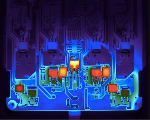
Infrared imaging, often performed with a thermal camera, offers a non-contact method to visualize heat distribution across an entire PCB. These devices detect infrared radiation emitted by objects, translating it into a temperature map or thermogram. This approach is invaluable for identifying hot spots and assessing overall thermal patterns without physically touching the board.
When using a thermal camera, engineers must ensure proper calibration and consider factors like emissivity, which affects how much infrared radiation a surface emits. Measurements should be taken under controlled conditions to avoid interference from ambient heat sources. This method aligns with best practices in thermal analysis, as it provides a quick and comprehensive view of temperature distribution, aiding in design validation and troubleshooting.
Related Reading: Why Use Online Thermal Cameras for Temperature Monitoring?
Leveraging Temperature Sensors for Integrated Monitoring
Temperature sensors, such as thermistors or integrated circuit sensors, can be embedded on a PCB for continuous monitoring. These sensors are often smaller than thermocouples and can be directly soldered or mounted onto the board during assembly. They provide real-time data, making them suitable for dynamic testing under operational conditions.
Engineers must select sensors with appropriate sensitivity and range for the expected temperature profile of the PCB. Placement near high-power components or critical areas ensures accurate readings. Data from these sensors can be logged over time to analyze thermal behavior during different operating modes, supporting compliance with performance standards like IPC-6012E.
Utilizing Simulation Tools for Predictive Thermal Analysis
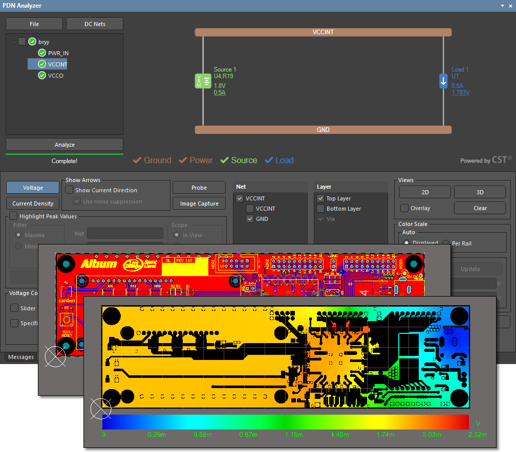
Simulation software allows engineers to predict PCB thermal performance before physical prototypes are built. These tools use finite element analysis or computational fluid dynamics to model heat generation, conduction, and dissipation based on design parameters. Simulation is a cost-effective way to test multiple scenarios and optimize layouts for thermal efficiency.
To conduct a simulation, engineers input data such as component power dissipation, board materials, and ambient conditions. The software then generates a virtual heat map, highlighting potential issues. While simulations are not a replacement for physical testing, they provide valuable insights during the design phase, reducing the need for costly revisions. Adhering to material and design guidelines from JEDEC J-STD-020E ensures that simulation inputs are realistic and relevant.
Related Reading: Thermal PCB design
Best Practices for Accurate Thermal Measurements
Achieving reliable results when measuring PCB thermal performance requires careful planning and execution. Below are key practices to follow across all methods discussed:
- Standardize Test Conditions: Conduct measurements in a controlled environment to minimize variables like ambient temperature or airflow. Consistency aligns with quality management principles in ISO 9001:2015.
- Calibrate Equipment Regularly: Ensure that thermocouples, thermal cameras, and temperature sensors are calibrated according to manufacturer specifications or industry standards.
- Document Sensor Placement: Record the exact locations of sensors or imaging focus areas to replicate tests and validate results over time.
- Combine Multiple Methods: Use a combination of contact and non-contact techniques to cross-verify data. For instance, pair thermocouple readings with infrared imaging for comprehensive analysis.
- Account for Material Properties: Consider the thermal conductivity and emissivity of PCB materials when interpreting results, especially in simulations or infrared measurements.
Following these practices helps engineers obtain accurate data, which is critical for meeting performance and reliability requirements outlined in standards like IPC-A-600K.
Troubleshooting Common Thermal Issues on PCBs
Identifying and resolving thermal issues is a key application of the measurement techniques discussed. Hot spots often indicate poor heat dissipation or overloaded components. Using a thermal camera can quickly reveal these areas, while thermocouples provide precise temperature values at specific points. If simulations predicted lower temperatures than measured, it might suggest inaccuracies in input data or unaccounted heat sources.
Engineers should also check for uneven heat distribution, which could result from improper trace layout or insufficient vias for heat transfer. Adjusting the design to include more thermal vias or optimizing component placement can mitigate such issues. Continuous monitoring with temperature sensors during operation helps detect intermittent problems that static tests might miss. Addressing these challenges ensures that the PCB performs reliably under real-world conditions.
Suggested Reading: Mastering Thermal Vias: Essential Heat Management for High-Power PCBs
Conclusion
Measuring PCB thermal performance is a fundamental task for electrical engineers aiming to design reliable and efficient electronic systems. Techniques such as thermocouples, infrared imaging with thermal cameras, temperature sensors, and simulation tools each offer unique benefits for capturing and analyzing heat data. By combining these methods and adhering to industry standards, engineers can identify thermal issues, validate designs, and implement effective solutions. A thorough understanding of thermal behavior not only enhances PCB reliability but also contributes to the overall success of electronic products in demanding applications.
FAQs
Q1: How do thermocouples help in measuring PCB thermal performance?
A1: Thermocouples provide precise temperature readings at specific points on a PCB by direct contact. They are ideal for monitoring critical components or validating thermal models. Engineers attach them to target areas and record data via a logger, ensuring accurate insights into localized heat, which is essential for design optimization and compliance with industry standards.
Q2: What are the advantages of using a thermal camera for PCB analysis?
A2: A thermal camera offers non-contact measurement, capturing heat distribution across an entire PCB as a visual thermogram. It quickly identifies hot spots and uneven heating without physical interference. This method is efficient for troubleshooting and validating designs, making it a valuable tool for electrical engineers focusing on thermal performance.
Q3: How does simulation improve PCB thermal management?
A3: Simulation tools predict PCB thermal behavior using virtual models, allowing engineers to test designs before fabrication. By inputting component and material data, simulations highlight potential hot spots and guide layout adjustments. This predictive approach saves time and resources, enhancing thermal management during the early stages of development.
Q4: Why are temperature sensors useful for long-term PCB monitoring?
A4: Temperature sensors, embedded on a PCB, enable continuous monitoring during operation. They provide real-time data near critical components, helping detect dynamic thermal changes over time. This capability is crucial for identifying intermittent issues and ensuring the board operates within safe limits under varying conditions.
References
IPC-6012E — Qualification and Performance Specification for Rigid Printed Boards. IPC, 2020.
IPC-A-600K — Acceptability of Printed Boards. IPC, 2020.
JEDEC J-STD-020E — Moisture/Reflow Sensitivity Classification. JEDEC, 2014.
ISO 9001:2015 — Quality Management Systems. ISO, 2015.


