Introduction
Functional safety plays a critical role in railway signaling systems where printed circuit boards form the backbone of control electronics. These PCBs manage vital functions such as trackside signaling, interlocking logic, and train detection, all operating under demanding environmental conditions. Implementing functional safety ensures that potential failures do not lead to hazardous events like derailments or collisions. Engineers must integrate safety principles from the initial PCB design phase to achieve required SIL ratings through rigorous risk assessment and robust design choices. Railway applications demand PCBs that withstand vibration, temperature extremes, and electromagnetic interference while maintaining high reliability. This article explores structured approaches to PCB design that align with functional safety requirements for enhanced system integrity.
What Is Functional Safety and Why It Matters in Railway Applications
Functional safety refers to the part of overall safety that depends on the correct functioning of safety-related electrical and electronic systems to avoid dangerous failures. In railway signaling, it addresses risks from malfunctions in PCBs that control safety functions like automatic train protection or level crossing signals. Safety Integrity Levels, or SIL ratings, quantify the reliability of these functions, with SIL 1 offering basic integrity and SIL 4 providing the highest level for catastrophic risk reduction. Higher SIL ratings require more stringent design measures, including fault tolerance and diagnostic coverage. Railway applications prioritize functional safety because signaling failures can endanger lives, disrupt operations, and incur massive costs. Compliance with standards like IEC 61508 guides engineers in lifecycle management from concept to decommissioning, ensuring tolerable risk levels through systematic processes.
The relevance stems from the high consequence of failures in signaling PCBs, where even rare faults must be mitigated. Risk assessment identifies hazards early, determining the necessary SIL for each safety function. For instance, vital signaling relays often target SIL 2 or higher to meet probabilistic failure targets. Without functional safety, systems lack verifiable integrity, leading to regulatory non-compliance and operational bans. Engineers benefit from understanding SIL implications during PCB design to avoid costly redesigns. Ultimately, functional safety elevates PCB design from mere functionality to proven safety performance in harsh rail environments.
Key Technical Principles of Functional Safety in PCB Design
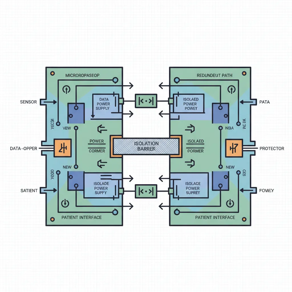
Functional safety principles in PCB design revolve around reducing systematic and random failures to meet SIL targets. Systematic failures arise from design errors, while random ones follow probabilistic models analyzed via FMEDA. IEC 61508 outlines hardware architectural constraints, such as single or multiple channels with diagnostic coverage, to achieve target failure measures. For railway signaling, PCBs must support redundancy, like dual power paths or diverse processing elements, to detect and respond to faults. Probability of failure on demand and dangerous failure rates define SIL achievement, demanding low component failure rates and high diagnostic efficiency.
Mechanisms include separation of safety-critical traces from non-critical ones to prevent common-cause failures. Layout strategies minimize single points of failure, using guard rings and isolation barriers. Component selection emphasizes derating, operating below maximum ratings for voltage, current, and temperature to extend mean time between failures. Thermal management principles ensure even heat distribution via thicker copper planes and vias. Vibration resistance incorporates wider traces and anchored components. These principles form a structured framework for PCB design tailored to railway signaling demands.
Conducting Risk Assessment for Railway Signaling PCBs
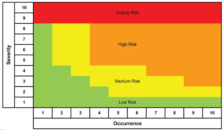
Risk assessment initiates the functional safety process by identifying hazards and assigning SIL ratings to PCB-related safety functions. Preliminary Hazard Analysis (PHA) catalogs potential dangers, such as signal misinterpretation from PCB shorts or opens. Failure Mode and Effects Analysis (FMEA) then evaluates each PCB element, scoring severity, occurrence, and detectability to prioritize mitigations. For railway applications, this includes environmental stressors like shock and humidity impacting solder joints or delamination.
Quantitative risk assessment computes tolerable hazard rates, mapping to SIL via target failure probabilities. Engineers perform subsystem FMEAs on power supplies, signal processing, and interfaces, identifying dominant failure modes like via cracks under vibration. Layered assessments, from system to component level, ensure comprehensive coverage. Documentation traces risks to design controls, facilitating independent review. Regular updates during design iterations maintain alignment with evolving requirements. This methodical risk assessment underpins defensible SIL claims for signaling PCBs.
Best Practices for PCB Design Achieving SIL Ratings in Railway Applications
Achieving required SIL ratings demands integrated best practices across material selection, layout, and manufacturing in PCB design. Select laminates with high glass transition temperature (Tg) above 170°C to resist delamination in thermal cycling common to railways. Thicker copper foils, such as 2 oz or more on power layers, enhance current capacity and mechanical strength against vibration. Surface finishes like electroless nickel immersion gold provide reliable solderability and corrosion resistance for long-term exposure.
Layout practices emphasize redundancy and fault isolation. Duplicate critical traces on separate layers with monitoring circuits to detect discrepancies. Maintain minimum clearances for high-voltage sections per insulation coordination rules, using slots or moats for creepage enhancement. Controlled impedance traces for high-speed signals reduce EMI risks, vital for signaling integrity. Ground planes shield sensitive analog sections, with stitching vias to lower inductance. Component placement groups high-heat devices near edges for airflow, incorporating thermal vias under ICs.
Mechanical robustness features include increased board thickness to 2.0 mm or more, reducing flexure under shock. Through-hole components for high-vibration areas offer superior anchorage over SMT alone. Conformal coatings, such as parylene, protect against moisture ingress and contaminants. EMC mitigation involves ferrite beads on I/O lines and multi-stage filtering for conducted emissions. Derating policies limit stresses to 70-80% of ratings, boosting reliability margins.
Manufacturing alignment with IPC-6012E qualification specifications ensures via integrity and plating uniformity. Solder joint reliability follows J-STD-001 guidelines, with ionic cleanliness testing to prevent dendrite growth. These practices collectively lower random failure rates and systematic errors, supporting SIL verification.
Verification, Validation, and Testing for Functional Safety
Verification confirms design adherence to safety requirements through reviews and simulations. Validation tests prototypes under operational profiles, including temperature cycling and random vibration per railway profiles. Diagnostic coverage testing quantifies fault detection efficacy for SIL credit. Independent assessment bodies audit safety cases, including FMEDA results. Lifecycle testing accelerates aging to predict 20-30 year service life. Traceability matrices link requirements to evidence, ensuring auditable compliance.
Conclusion
Implementing functional safety in railway signaling PCB design requires a holistic approach from risk assessment to validated deployment. Key elements like SIL-targeted architectures, robust materials, and rigorous verification ensure reliable performance. Engineers achieve this through structured practices that mitigate failures in demanding environments. Prioritizing these principles not only meets regulatory demands but also enhances overall system safety.
FAQs
Q1: What role does risk assessment play in determining SIL rating for railway signaling PCBs?
A1: Risk assessment identifies hazards and failure modes in PCB design, quantifying tolerable risks to assign appropriate SIL ratings. Methods like FMEA evaluate component vulnerabilities under railway conditions such as vibration and thermal stress. This process guides mitigations like redundancy, ensuring the PCB achieves probabilistic targets for functional safety. Logical prioritization prevents overdesign while securing compliance.
Q2: How does IEC 61508 influence PCB design for functional safety in railway applications?
A2: IEC 61508 provides lifecycle guidelines for safety-related systems, mandating architectural constraints and diagnostic coverage in PCB design. For railways, it informs redundancy and fault detection to meet SIL requirements in signaling. Engineers apply its principles to materials, layout, and verification for reduced failure probabilities. This standard ensures systematic integrity across development phases.
Q3: What are essential best practices for PCB layout to support high SIL ratings?
A3: Best practices include redundant channels, isolation barriers, and derated components to minimize common-cause failures in railway signaling. Wider traces and ground planes enhance EMI immunity and mechanical strength. Controlled impedances preserve signal integrity under vibration. These structured choices align with functional safety goals for reliable operation.
Q4: Why is material selection critical for functional safety in railway PCB design?
A4: High-Tg laminates and thick copper prevent delamination and cracking in harsh railway environments, supporting SIL targets. Finishes like ENIG ensure long-term solder joint reliability. Derating compatible materials extend MTBF, vital for safety functions. Selection directly impacts random failure rates in risk assessments.
References
IEC 61508 — Functional safety of electrical/electronic/programmable electronic safety-related systems. IEC.
IPC-6012E — Qualification and Performance Specification for Rigid Printed Boards. IPC, 2017.
J-STD-001H — Requirements for Soldered Electrical and Electronic Assemblies. IPC, 2018.
IPC-TM-650 — Test Methods Manual. IPC.


