Introduction
Navigation systems rely on printed circuit boards (PCBs) to process signals from sensors and satellites in real-time, ensuring accurate positioning in vehicles, aircraft, and vessels. These PCBs operate in harsh environments characterized by extreme temperatures, high vibration, excessive humidity, and mechanical shock, which can lead to failures like delamination, corrosion, or solder joint cracks. Improving PCB reliability involves targeted strategies such as conformal coating, environmental testing, thermal management, vibration resistance, and humidity control. Engineers must integrate these approaches during design and manufacturing to meet performance demands without compromising functionality. This article explores practical engineering solutions tailored for electric engineers working on navigation applications. By addressing these factors systematically, navigation PCBs can achieve extended mean time between failures (MTBF) in demanding conditions.
Challenges Faced by Navigation PCBs in Harsh Environments
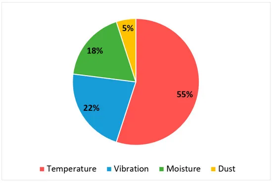
Navigation PCBs encounter multifaceted stresses that accelerate degradation mechanisms. Temperature fluctuations cause thermal expansion mismatches between copper traces, substrates, and components, potentially inducing cracks in vias or pads. Vibration from engines or rough terrain generates cyclic mechanical loads, leading to fatigue in solder joints and trace fractures. High humidity promotes electrochemical migration and corrosion, especially at exposed metallic surfaces, while dust and salt ingress exacerbate wear in marine or off-road settings. These combined stressors demand robust design choices from the outset. Engineers evaluate failure modes using physics-of-failure analysis to prioritize mitigation strategies effectively.
Navigation PCB Conformal Coating: A Primary Defense Layer
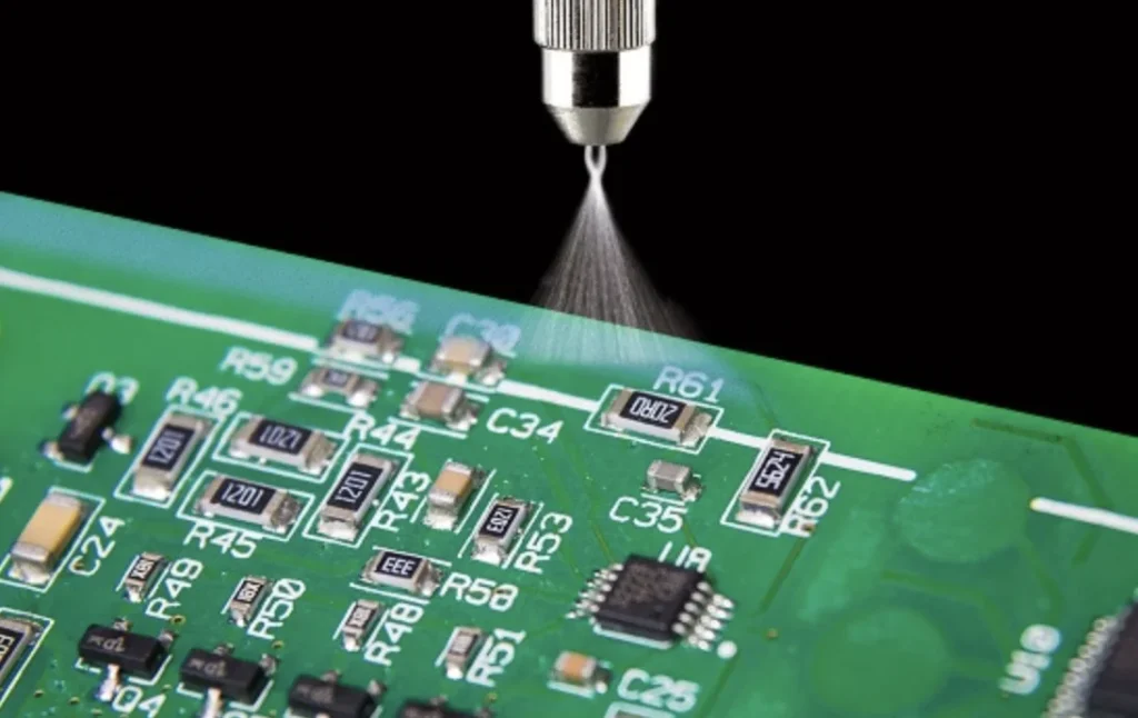
Conformal coating applies a thin polymeric film over the assembled PCB to protect against moisture, chemicals, and abrasion. This barrier prevents ionic contamination and dendritic growth under humidity bias, common in navigation systems exposed to condensation. Materials must balance flexibility to accommodate thermal cycling with adhesion to prevent peeling during vibration. Selective application techniques, such as masking critical areas like connectors, ensure signal integrity while covering vulnerable components. Thickness uniformity, typically controlled between 25 to 250 microns, enhances dielectric strength and fault tolerance. Adherence to IPC-CC-830 guidelines ensures coating qualification through tests like humidity exposure and thermal shock, validating long-term performance.
Application methods include dip, spray, or brush, selected based on PCB geometry and production volume. Pre-coating cleaning removes flux residues to promote bonding, while post-cure inspection verifies coverage voids using UV fluorescence. In navigation contexts, coatings mitigate risks from salt fog in coastal operations or fuel vapors in aerospace. Engineers simulate aged coatings via accelerated life testing to predict field reliability. Proper edge coverage prevents creepage under high voltage differentials typical in power regulation sections.
Navigation PCB Environmental Testing: Validating Durability
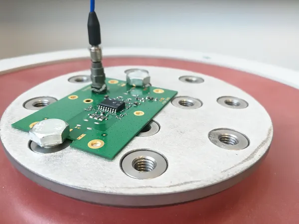
Environmental testing simulates operational stresses to uncover weaknesses before deployment. Protocols include temperature cycling from -55°C to 125°C, mimicking avionics extremes, to assess expansion coefficient compatibility. Humidity testing at 85% relative humidity and elevated temperatures reveals corrosion susceptibility and insulation resistance degradation. Vibration profiles follow sinusoidal or random spectra up to 20g RMS, evaluating mechanical integrity of terminations. Shock tests replicate drop or collision impacts, checking for dislodged parts. These sequences align with IPC-6012E qualification for rigid boards in high-reliability classes.
Test chambers maintain precise profiles, with PCBs monitored via strain gauges or daisy-chain networks for early failure detection. Post-test analysis involves cross-sectioning to inspect microcracks or intermetallic growth. Navigation-specific tests incorporate combined stressors, like vibration under thermal soak, to replicate mission profiles. Data loggers capture real-time parameters, enabling statistical reliability modeling such as Weibull analysis. Iterative testing refines designs, ensuring compliance with performance specifications.
Navigation PCB Thermal Management: Dissipating Heat Effectively
Effective thermal management prevents hotspots that degrade components in power-intensive navigation processors. Copper planes and filled vias conduct heat from ASICs to outer layers, reducing junction temperatures. Material selection favors high thermal conductivity laminates with low coefficients of thermal expansion (CTE) to minimize warpage. Via stitching arrays under hot spots distribute heat laterally, while embedded heat pipes suit compact designs. Component placement optimizes airflow paths, avoiding stacking high-power devices.
Simulation tools model transient responses during signal bursts, guiding sink attachment or potting compounds. Phase change materials absorb peaks in pulsed operations common in radar-integrated navigation. Monitoring via thermocouples during qualification confirms margins over maximum ratings. Integration with chassis cooling enhances system-level dissipation. These techniques extend component life by adhering to derating guidelines.
Navigation PCB Vibration Resistance: Mechanical Fortification
Vibration resistance starts with layout strategies that minimize resonant amplification. Traces routed perpendicular to vibration axes reduce flexing, while wider conductors lower impedance to fatigue. Component anchoring uses underfill or corner stakes to secure BGAs against shear forces. Stiffeners or metal frames reinforce board edges, distributing loads evenly. Solder joint geometry, fillet height, and alloy choice influence shear strength under harmonic excitation.
Finite element analysis predicts modes, allowing damping material placement at nodes. Compliance testing per relevant profiles verifies no opens or intermittents post-exposure. Hybrid stacking with cores provides rigidity without excess weight. Edge connectors with compliant pins absorb deflections. These measures ensure signal stability in high-g environments like tactical vehicles.
Navigation PCB Humidity Control: Preventing Moisture Ingress
Humidity control complements conformal coating through material handling and enclosure design. Moisture sensitivity levels (MSL) dictate baking prior to reflow, per JEDEC J-STD-020E, to desorb absorbed water and avert popcorning. Hermetic sealing or gaskets block vapor diffusion in enclosures. Desiccant packs maintain low dew points during storage. Selective venting equalizes pressure without moisture entry.
Assembly in controlled cleanrooms limits initial contamination. Ionic cleanliness testing post-process confirms low residue levels. Bake-out cycles precondition boards for humid climates. Multi-layer barriers, including parylene over acrylic, provide redundancy. System-level humidity sensors trigger alarms, enabling predictive maintenance. These controls preserve electrical performance over years.
Integrating Best Practices for Optimal Reliability
Successful navigation PCBs combine these elements holistically. Design reviews incorporate DFMEA to rank risks, prioritizing coating for humidity-prone areas and stiffening for vibration hotspots. Material datasheets specify Tg above 170°C and Td over 300°C for thermal resilience. Prototyping iterates on test feedback, refining mask layouts or via patterns. Supply chain qualification ensures lot-to-lot consistency. Documentation traces changes, supporting field diagnostics. This integrated approach yields PCBs robust for decade-long missions.
Conclusion
Enhancing navigation system PCB reliability in harsh environments demands a multifaceted strategy encompassing conformal coating, rigorous environmental testing, advanced thermal management, vibration-resistant designs, and precise humidity control. Each technique addresses specific failure modes while interlocking for synergistic protection. Electric engineers benefit from standards-guided processes that ensure repeatability and performance. Implementing these practices minimizes downtime and safety risks. Future advancements in nanomaterials promise further gains, but current methods suffice for demanding applications today.
FAQs
Q1: What role does navigation PCB conformal coating play in harsh environments?
A1: Conformal coating forms a protective dielectric layer that shields against humidity, dust, and chemicals, preventing corrosion and short circuits. It maintains adhesion under thermal cycling and vibration, as qualified by IPC-CC-830 tests. Engineers select materials based on flexibility and cure properties for navigation-specific exposures. Proper application avoids coverage defects, ensuring long-term insulation resistance. This enhances overall board survivability without altering electrical characteristics significantly.
Q2: How is navigation PCB environmental testing conducted for reliability?
A2: Testing involves sequential stresses like thermal cycling, humidity bias, and random vibration to simulate operational profiles. Chambers control parameters precisely, with in-situ monitoring for failures. Post-test dissections reveal root causes such as microcracking. Alignment with IPC-6012E class 3 ensures high-reliability qualification. Results guide design iterations for navigation systems in extremes.
Q3: Why is navigation PCB thermal management critical in high-power applications?
A3: Thermal management dissipates heat from processors and amplifiers, preventing derating or failure. Techniques like thermal vias and copper pours lower theta JA effectively. Modeling predicts hotspots during peak loads. This sustains performance in enclosed, hot environments typical for navigation. Integration with system cooling optimizes margins.
Q4: What strategies improve navigation PCB vibration resistance?
A4: Strategies include trace routing optimization, component underfill, and mechanical stiffeners to counter fatigue. Resonance avoidance via FEA directs damping additions. Robust solder joints withstand g-levels. Testing validates no parametric shifts post-exposure. These fortify boards for dynamic navigation platforms.
References
IPC-CC-830C — Qualification and Performance of Electrical Insulating Compounds for Coating Printed Wiring Boards. IPC.
IPC-6012E — Qualification and Performance Specification for Rigid Printed Boards. IPC, 2017.
JEDEC J-STD-020E — Moisture/Reflow Sensitivity Classification for Nonhermetic Surface Mount Devices. JEDEC, 2014.
IEC 60068 — Environmental Testing. IEC.


