Introduction
Infotainment systems serve as the central hub for modern vehicle entertainment, navigation, and connectivity features. These systems integrate high-speed processors, displays, cameras, and wireless modules onto printed circuit boards (PCBs) that must endure automotive environments, including temperature swings from -40°C to 125°C, constant vibration, and electromagnetic interference. Manufacturing these PCBs demands precision to prevent failures that could compromise driver safety or system performance. The PCB assembly process automotive emphasizes reliability through controlled material handling, soldering, and inspection stages. By following established best practices, manufacturers achieve consistent quality suitable for high-volume production. This article explores key techniques tailored to infotainment applications.
Why Best Practices Matter in Infotainment PCB Manufacturing
Infotainment PCBs process mixed signals, power delivery, and data at high densities, making them susceptible to defects like delamination or solder joint cracks under thermal cycling. Poor manufacturing leads to field returns, warranty costs, and reputational damage in the competitive automotive sector. Adopting rigorous processes aligns production with performance demands, extending board lifespan beyond 10 years in vehicles. Factory-driven insights reveal that proactive measures in assembly reduce defect rates by focusing on repeatability and traceability. Ultimately, these practices ensure compliance with reliability expectations in demanding applications.
Key Stages in the PCB Assembly Process for Automotive Infotainment
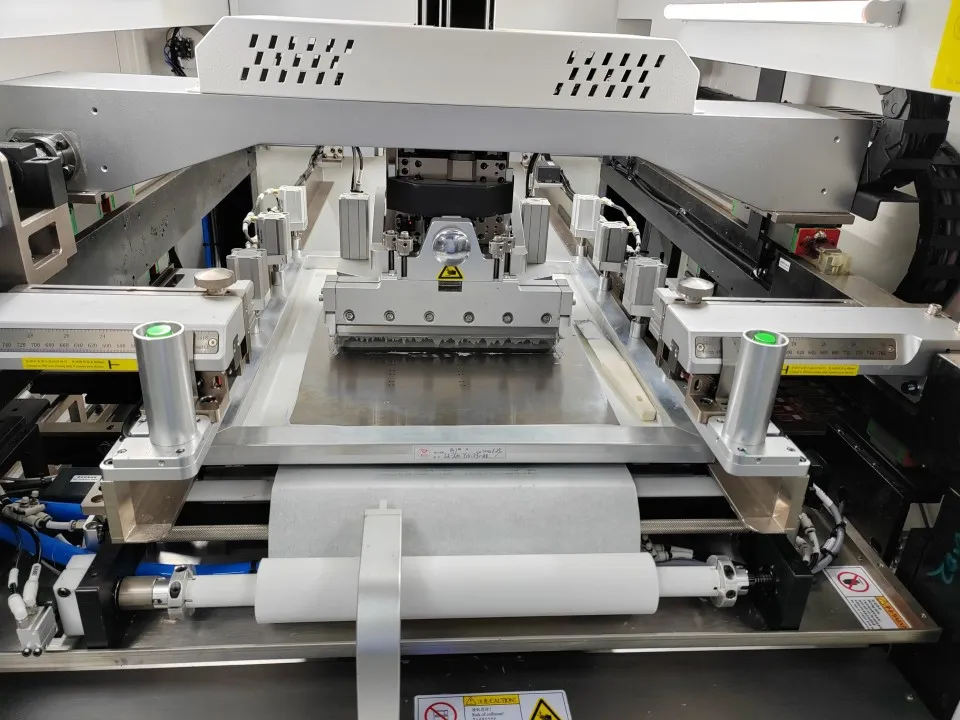
The PCB assembly process automotive begins with solder paste printing using laser-cut stencils optimized for fine-pitch components common in infotainment boards. Stencils feature thicknesses of 0.1 to 0.15 mm to deposit uniform paste volumes, preventing insufficient wetting or bridging on pads. Automated paste inspection verifies deposit height and alignment before proceeding. Component placement follows via high-speed pick-and-place machines calibrated for 01005 passives and BGAs. Machines use vision systems to achieve ±20 μm accuracy, critical for signal integrity in high-frequency circuits. Dual-lane systems boost throughput for mixed-technology boards.
Post-placement verification confirms component presence and orientation. For infotainment PCBs, selective fiducials aid machine alignment on multi-panel arrays. This stage minimizes rework by catching misplacements early.
Reflow Soldering Techniques for Automotive PCBs
Reflow soldering techniques PCB dominate surface-mount assembly due to their compatibility with dense layouts in infotainment systems. Solder paste, typically lead-free SAC305, undergoes a multi-zone profile: preheat to 150°C removes flux volatiles, soak at 180°C ensures even heating, reflow peak at 245°C forms joints, and cooling solidifies without thermal shock. Nitrogen atmospheres reduce oxidation, improving joint cosmetics and reliability under humidity. Profile validation uses thermocouples on test coupons to match oven settings precisely.
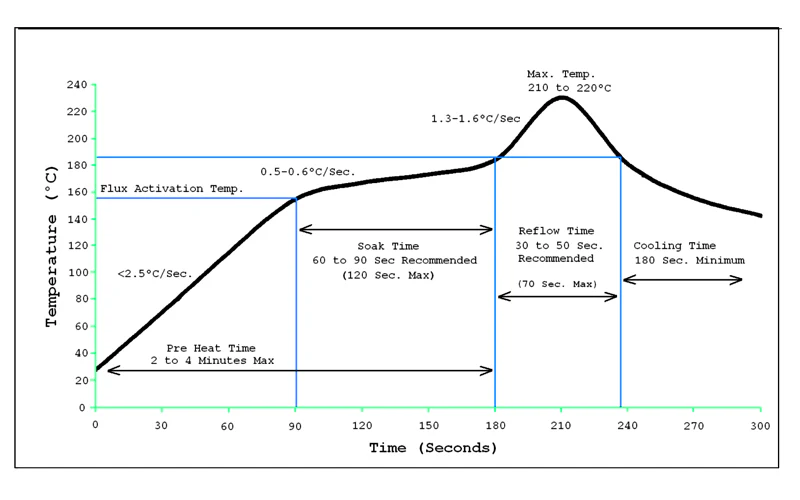
Warpage control proves essential, as infotainment boards with copper-filled vias expand differently during heating. Manufacturers preheat carriers or use low-standoff components to maintain planarity below 0.75% per IPC standards. Voiding in BGA balls, monitored via X-ray, stays under 25% through optimized paste formulations and ramp rates. These techniques yield robust joints resistant to vibration-induced fatigue.
Wave Soldering for Through-Hole Components in Infotainment PCBs
Wave soldering infotainment PCBs suits through-hole (THT) elements like connectors and electrolytic capacitors, which handle mechanical stress in vehicle dashboards. Boards enter on pallets masking SMT areas to prevent solder contamination. Flux application via spray ensures clean wetting, followed by preheating to 100-120°C for flux activation and moisture removal. The solder wave, at 250-260°C, contacts pins at a 7-10° angle to minimize bridging.
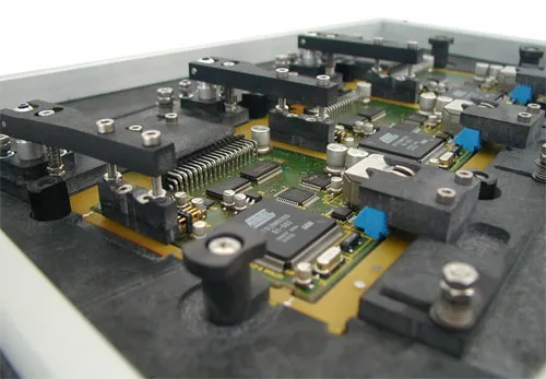
Component orientation directs trailing pins away from dense areas, reducing turbulence effects. Post-wave cleaning removes flux residues with deionized water or vapor degreasing to prevent dendritic growth. Pallet fixturing maintains coplanarity, ensuring full pin immersion without shadowing. This process integrates seamlessly with SMT reflow for hybrid boards.
Automated Optical Inspection (AOI) in PCB Quality Control
Automated optical inspection (AOI) PCB occurs inline after printing, placement, and reflow to detect defects non-destructively. High-resolution cameras with multi-angle LED lighting capture 2D or 3D images, comparing against golden samples or CAD data. Systems flag missing components, polarity errors, solder bridges, and insufficient paste with false call rates below 500 ppm. For infotainment PCBs, 3D AOI measures joint height and coplanarity, vital for BGA reliability.
Programming accounts for shadow effects from tall components, using algorithms trained on automotive profiles. Integration with manufacturing execution systems (MES) enables real-time yield analytics. AOI reduces escapes to functional test, aligning with IPC-A-610 Class 3 criteria for high-reliability assemblies.
Additional Best Practices for Reliability and Yield
Conformal coating application post-assembly protects against moisture and contaminants in under-hood or cabin environments. Selective spraying or dipping follows masking of connectors, cured via UV or thermal ovens. Functional and in-circuit testing verifies signal paths and power integrity under simulated loads.
Traceability via barcodes links lots to process data, aiding root-cause analysis. Bake-out before assembly removes moisture per JEDEC guidelines, preventing popcorn cracks. These steps, combined with statistical process control, sustain yields above 98%.
Troubleshooting Common Manufacturing Challenges
Thermal mismatch causes head-in-pillow defects in reflow, resolved by matching CTE between components and boards. Vibration testing post-assembly simulates road conditions, identifying weak joints early. Bridging in wave soldering traces to flux drag-out, corrected by nozzle adjustments and drag height optimization.
Solder balling from paste residue demands stencil cleaning every 10 prints. Proactive SPC charts track CpK values, triggering maintenance before drifts occur.
Conclusion
Manufacturing infotainment system PCBs requires integrating precise PCB assembly process automotive with advanced reflow soldering techniques PCB, wave soldering infotainment PCBs, and automated optical inspection (AOI) PCB. These practices ensure boards withstand automotive rigors while meeting production volumes. Factory focus on standards and process control delivers reliable outcomes. Engineers benefit from structured approaches that minimize variability and enhance longevity.
FAQs
Q1: What are the main steps in the PCB assembly process automotive for infotainment systems?
A1: The PCB assembly process automotive starts with solder paste printing, followed by high-precision component placement, reflow soldering for SMT, and wave or selective soldering for THT. Inspection via AOI and cleaning precede functional testing. Traceability ensures compliance, reducing defects in vibration-prone environments. This sequence supports high-density boards reliably.
Q2: How do reflow soldering techniques PCB improve automotive reliability?
A2: Reflow soldering techniques PCB use controlled nitrogen profiles to form void-free joints resistant to thermal cycling. Preheat and soak phases prevent tombstoning, while peak temperatures melt SAC alloys uniformly. Validation with thermocouples maintains consistency across runs. These methods align with high-reliability needs for infotainment signals.
Q3: When is wave soldering used for infotainment PCBs and what are best practices?
A3: Wave soldering infotainment PCBs applies to THT connectors needing mechanical strength. Best practices include pallet masking for SMT protection, 7° board angle, and post-flux preheating. Cleaning removes residues to avoid corrosion. Orientation minimizes bridging, ensuring robust assemblies.
Q4: Why is automated optical inspection (AOI) PCB essential in automotive manufacturing?
A4: Automated optical inspection (AOI) PCB detects solder defects, misalignments, and missing parts inline, preventing field failures. 3D capabilities measure joint volume for BGA integrity. Real-time feedback optimizes upstream processes like paste printing. It upholds Class 3 quality in high-volume production.
References
IPC-A-610H — Acceptability of Electronic Assemblies. IPC, 2019
J-STD-001G — Requirements for Soldered Electrical and Electronic Assemblies. IPC, 2011
IPC-6012E — Qualification and Performance Specification for Rigid Printed Boards. IPC, 2017