Introduction
Selecting the appropriate PCB substrate is a foundational decision in electronics manufacturing that directly influences performance, reliability, and cost. Organic substrates, such as those based on epoxy resins like FR4, dominate standard applications due to their versatility and affordability. In contrast, inorganic substrates, primarily ceramics, excel in demanding environments requiring superior thermal management and stability. This PCB substrate comparison explores the differences between organic PCB vs inorganic PCB materials, helping electric engineers make informed choices during PCB material selection. Factory insights reveal that mismatched substrates often lead to failures like delamination or warpage under thermal stress. Understanding these materials through a structured lens ensures alignment with project specifications and industry benchmarks.
As projects evolve toward higher power densities and harsher conditions, the debate between FR4 vs organic PCB variants and ceramic PCB vs organic PCB options intensifies. Organic materials suit volume production, while inorganic ones address niche high-reliability needs. Engineers must weigh properties like thermal conductivity and coefficient of thermal expansion (CTE) against processing constraints. This article draws from manufacturing perspectives to provide actionable guidance on PCB substrate comparison. By examining technical principles and best practices, readers gain clarity on optimizing designs for longevity and efficiency.
What Are Organic PCB Substrates?
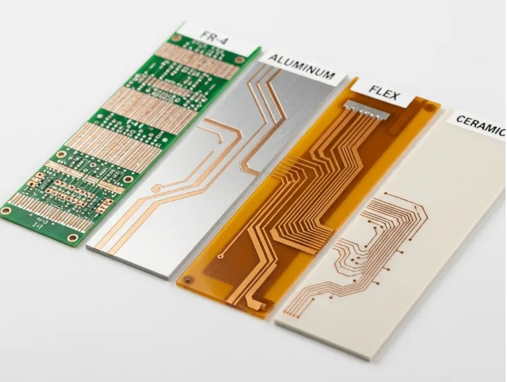
Organic PCB substrates consist of polymer matrices reinforced with glass fibers or other fillers, forming the core of most rigid printed boards. Common examples include FR4, which features a flame-retardant epoxy resin impregnated in woven glass cloth. These materials offer excellent electrical insulation and mechanical strength for general-purpose applications. From a factory standpoint, organic substrates enable high-volume lamination processes, supporting multilayer builds up to dozens of layers. Their dielectric properties support signal integrity in mid-range frequencies.
The composition allows for straightforward drilling, plating, and soldering, aligning with standard PCB fabrication flows. However, organic substrates exhibit limitations in extreme temperatures due to glass transition temperature (Tg) thresholds. Moisture absorption can alter dimensions and electrical performance over time. IPC-4101E classifies these base materials by performance grades, ensuring consistency in qualification tests. Factories prioritize organic substrates for cost-sensitive projects where thermal demands remain moderate.
What Are Inorganic PCB Substrates?
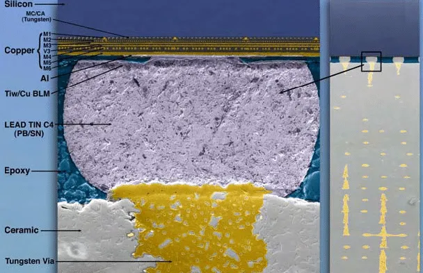
Inorganic PCB substrates, predominantly ceramics like alumina or aluminum nitride, derive from non-carbon-based compounds sintered at high temperatures. These materials provide a rigid, non-polymeric base ideal for harsh environments. Ceramic substrates boast inherent thermal conductivity far exceeding organics, facilitating heat dissipation without additional vias or planes. Manufacturing involves thin-film or thick-film deposition, often requiring specialized cleanroom processes. Their hermetic nature resists environmental ingress, enhancing long-term reliability.
Unlike organics, inorganic substrates maintain dimensional stability across wide temperature swings, minimizing CTE mismatches with attached components. This property proves critical in power electronics and RF modules. Processing challenges include higher brittleness, necessitating careful handling to avoid cracks during dicing or mounting. Standards like IPC-6012E guide qualification for both organic and inorganic boards, emphasizing visual and electrical inspections. Factories reserve inorganic substrates for applications where failure is not an option.
Key Differences in PCB Substrate Comparison
A direct PCB substrate comparison highlights stark contrasts in physical properties, driving material selection decisions. Organic substrates generally feature lower thermal conductivity, relying on copper planes for heat spreading, while inorganic ones conduct heat intrinsically through the base. CTE values in organics lead to greater expansion, potentially stressing solder joints, whereas ceramics closely match silicon dies. Moisture absorption plagues organics, risking popcorn effects during reflow, but ceramics remain impervious.
Dielectric constants differ, with organics offering stable values for most signals and ceramics providing low loss at high frequencies. Cost structures favor organics for scalability, as large panels reduce per-unit expenses, contrasting with ceramics’ premium pricing due to raw material and processing. Machinability is easier for organics, supporting standard CNC routing, while ceramics demand diamond tooling. These traits influence design rules, from via densities to layer counts.
The following points summarize core attributes for quick reference in PCB material selection:
- Thermal Conductivity: Organic — Low (relies on metal layers); Inorganic — High (intrinsic material property)
- CTE: Organic — Higher (risk of mismatch); Inorganic — Low (matches semiconductors)
- Moisture Absorption: Organic — Moderate to high; Inorganic — Negligible
- Temperature Tolerance: Organic — Up to Tg limit (~130-180°C); Inorganic — Extreme (>200°C sustained)
- Cost: Organic — Low, volume-friendly; Inorganic — High, specialized
- Brittleness: Organic — Flexible, tough; Inorganic — Brittle, requires care
This comparison underscores why FR4 vs organic PCB discussions often center on everyday reliability versus ceramic PCB vs organic PCB for performance extremes.
Technical Principles Behind Performance
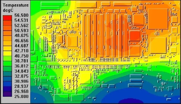
Thermal management forms the cornerstone of substrate efficacy, with inorganic materials dissipating heat via phonon conduction absent in organic polymers. Organics suffer from anisotropic conductivity, excelling in-plane but lagging through-thickness. JEDEC standards like JESD51 series outline test conditions for accurate thermal profiling, aiding simulations. CTE mismatch induces warpage, quantified in factory tests per IPC guidelines, where inorganic stability prevents bow exceeding 0.75% on panels.
Electrical performance hinges on dielectric loss tangent, lower in ceramics for microwave apps. Moisture in organics swells the resin, shifting impedance and risking shorts post-assembly. Reliability testing per IPC-6012E verifies endurance under thermal cycling, exposing organic vulnerabilities beyond 1000 cycles. Inorganic substrates shine in vibration-prone settings, their rigidity preserving trace integrity.
Warpage mechanisms differ fundamentally: organics warp from resin shrinkage, while ceramics resist due to uniform sintering. Factory data correlates substrate choice with yield, with organics hitting 99% in standard runs but dropping in high-heat profiles.
Practical Guidance for PCB Material Selection
Begin material selection by mapping project requirements to property profiles, prioritizing thermal load and operating temperature. For power densities below 1 W/cm2, organic FR4 suffices with embedded planes; exceed this, and ceramics become viable. Consult IPC-4101E grades for organics matching your Tg and Z-axis expansion needs. Prototype testing validates choices, focusing on reflow compatibility per JEDEC moisture classifications.
Layer stackups demand consideration: organics support blind/buried vias easily, while ceramics favor surface-mount or wire-bonding. Cost modeling includes tooling offsets, with organics amortizing over volume. Collaborate with fabricators early to align on tolerances, as inorganic processing alters lead times.
Best practices include hybrid approaches, like organic cores with ceramic heatspreaders for balanced performance. Simulate CTE impacts using factory-validated models to preempt failures.
Applications and Real-World Insights
Organic substrates power consumer electronics, automotive controls, and telecom boards where cost trumps extremes. FR4 variants handle up to 85-130°C reliably, suiting IoT and computing. Inorganic ceramics dominate aerospace, LED drivers, and RF amplifiers, enduring 200°C+ with minimal degradation. Factory case insights show ceramics extending MTBF in radar modules by stabilizing junctions.
In high-frequency 5G apps, ceramic low-loss tangents preserve signals, outperforming organics. Power inverters leverage inorganic thermal paths to cut cooling needs. Sustainability angles favor organics for recyclability, though ceramics offer longer lifecycles in critical uses.
Troubleshooting common issues: organic delamination traces to moisture; bake boards pre-assembly. Ceramic cracks stem from mishandling; use edge supports.
Conclusion
Organic and inorganic PCB substrates each claim strengths tailored to distinct needs, with organics excelling in affordability and scalability, and inorganics in thermal prowess and stability. PCB substrate comparison reveals no universal winner; project demands dictate the path. Factory-driven decisions, grounded in standards like IPC-4101E and IPC-6012E, optimize outcomes. Prioritize simulations and tests for PCB material selection to balance performance, cost, and reliability. Electric engineers equipped with this knowledge can confidently navigate FR4 vs organic PCB or ceramic PCB vs organic PCB choices, ensuring robust designs.
FAQs
Q1: What is the primary difference in organic PCB vs inorganic PCB substrates?
A1: Organic substrates rely on polymer resins like FR4 for cost-effective insulation and fabrication, exhibiting higher CTE and moisture sensitivity. Inorganic ceramics provide superior thermal conductivity and low expansion, ideal for high-heat apps. Factory qualification per IPC standards highlights organics for volume production and ceramics for reliability. This contrast drives PCB substrate comparison in material selection.
Q2: When should you choose ceramic PCB vs organic PCB?
A2: Opt for ceramics when thermal dissipation exceeds organic limits, such as in power electronics or RF, where low CTE prevents failures. FR4 suits general boards under moderate stress. Assess via JEDEC thermal tests to confirm. PCB material selection hinges on these profiles for optimal performance.
Q3: How does FR4 vs organic PCB fit into broader comparisons?
A3: FR4 represents standard organic PCBs, offering balanced properties for most designs, but shares organic drawbacks like limited conductivity. Comparisons extend to inorganic for extremes. Factory insights emphasize IPC-6012E compliance for both in qualification.
Q4: What factors influence PCB substrate comparison for electric engineers?
A4: Key factors include thermal conductivity, CTE matching, moisture resistance, and cost, evaluated against application specs. Standards guide testing for warpage and endurance. Practical selection ensures alignment with manufacturing capabilities.
References
IPC-4101E — Specification for Base Materials for Rigid and Multilayer Printed Boards. IPC, 2017
IPC-6012E — Qualification and Performance Specification for Rigid Printed Boards. IPC, 2017
JEDEC JESD51-2A — Integrated Circuits Thermal Test Method Environmental Conditions - Natural Convection. JEDEC, 2016


